基于網(wǎng)絡(luò)編碼的多信源組播通信系統(tǒng),包括源代碼,原理圖等 (三)

3 系統(tǒng)的詳細設(shè)計方案
本文引用地址:http://www.104case.com/article/201808/388146.htm3.1 概述
在組播網(wǎng)絡(luò)的拓撲圖中,編碼路由器、轉(zhuǎn)發(fā)路由器和解碼路由器是三個獨立的系統(tǒng),各自完成編碼、轉(zhuǎn)發(fā)和解碼的任務(wù)。前面講過,分組的編碼、解碼主要在網(wǎng)絡(luò)層完成。在網(wǎng)絡(luò)層中數(shù)據(jù)通道中,data bus和ctrl bus是同步傳輸?shù)模咧g的關(guān)系和格式如圖3.1-1所示:
ctrl bus(8位) | Data bus(64位) |
ff | module header |
00 | Pkt data1 |
00 | …… |
xy(xy≠00) | Last pkt data |
圖3.1-1 數(shù)據(jù)通道中的data bus和ctrl bus
Ctrl為ff時,表明為一個數(shù)據(jù)包的包頭,xy為非零數(shù)據(jù),指明最后一個有效的字節(jié)所在的位置,如01000000指明是第7個,即data[63:48]為有效數(shù)據(jù)。模塊之間數(shù)據(jù)傳輸?shù)倪^程是:若上一個模塊已經(jīng)處理完畢,想把數(shù)據(jù)傳輸?shù)较乱粋€模塊,首先判斷輸入信號rdy是否有效,當(dāng)rdy = 1時,將數(shù)據(jù)和控制信號同步發(fā)送出去,同時wr_vld信號有效,時序如圖3.1-2所示:
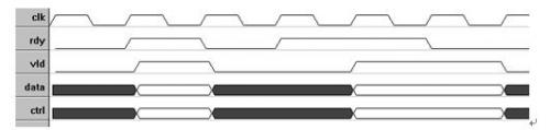
圖3.1-2 有效的數(shù)據(jù)傳輸時序
3.2 編碼路由器詳細設(shè)計方案
3.2.1編碼系統(tǒng)整體模塊如圖3.2-1所示
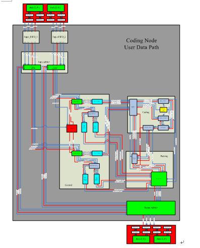
圖3.2-1:編碼系統(tǒng)整體模塊圖
3.2.2系統(tǒng)中各單元模塊的功能與時序
(1)Input arbiter
① Input arbiter內(nèi)部結(jié)構(gòu)如圖3.2-2所示:
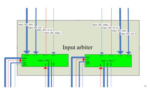
圖3.2-2 Input arbiter內(nèi)部結(jié)構(gòu)圖
② 本模塊輸入輸出信號列表及說明
Signal name | Bit width | Input or output | description |
Input_fifo_data_1 | 64 | input | Input data bus from “input FIFO 1” |
Input_fifo_ctrl_1 | 8 | input | Input ctrl bus from “input FIFO 1” |
Input_fifo_empty_1 | 1 | input | 1=input FIFO is empty,0=otherwise |
Input_fifo_rd_en_1 | 1 | output | Read enable |
Input_fifo_data_2 | 64 | input | Input data bus from “input FIFO 2” |
Input_fifo_ctrl_2 | 8 | input | Input ctrl bus from “input FIFO 2” |
Input_fifo_empty_2 | 1 | input | 1=input FIFO is empty,0=otherwise |
Input_fifo_rd_en_2 | 1 | output | Read enable |
Data_arbiter_ctrl_1 | 64 | output | Output data bus to “control module” |
Ctrl_arbiter_ctrl_1 | 8 | Output | Output ctrl bus to “control module” |
Val_arbitrer_ctrl_1 | 1 | Output | 1=data from input arbiter 1 to head splitter 1 is valid, 0=otherwise |
Rdy_arbiter_ctrl_1 | 1 | Input | 1=module “head splitter 1” is ready to receive |
Data_arbiter_ctrl_2 | 64 | output | Output data bus to “control module” |
Ctrl_arbiter_ctrl_2 | 8 | Output | Output ctrl bus to “control module” |
Val_arbitrer_ctrl_2 | 1 | Output | 1=data from input arbiter 2 to head splitter 2 is valid, 0=otherwise |
Rdy_arbiter_ctrl_2 | 1 | Input | 1=module “head splitter 2” is ready to receive, 0=otherwise |
Data_arbiter_out_1 | 64 | output | Output data bus to “output arbiter module” |
Ctrl_arbiter_out_1 | 8 | Output | Output ctrl bus to “output arbiter module” |
Val_arbiter_out_1 | 1 | Output | 1=data from input arbiter 1 to output arbiter is valid, 0=otherwise |
Rdy_arbiter_out_1 | 1 | Input | 1=module “output arbiter” is ready to receive from input arbiter 1, 0=otherwise |
Data_arbiter_out_2 | 64 | output | Output data bus to “output arbiter module” |
Ctrl_arbiter_out_2 | 8 | Output | Output ctrl bus to “output arbiter module” |
Val_arbiter_out_2 | 1 | Output | 1=data from input arbiter 2 to output arbiter is valid, 0=otherwise |
Rdy_arbiter_out_2 | 1 | Input | 1=module “output arbiter” is ready to receive from input arbiter 2, 0=otherwise |
clk | 1 | Input | System clock, running at 125MHz |
Rst_n | 1 | input | System asynchronous reset signal |
③ 功能描述及數(shù)據(jù)流
本模塊執(zhí)行輸入仲裁功能。兩個獨立的input arbiter模塊分別從兩個輸入FIFO讀出數(shù)據(jù)包,判斷數(shù)據(jù)包類型,決定輸出端口(非IP包直接送往output arbiter,IP包送往control),輸出數(shù)據(jù)。
為了判斷數(shù)據(jù)包類型,需要獲取16-bit Ether Type信息,該信息位于每個數(shù)據(jù)包第二個double word中的31:16位,若Ether Type為0x0080,則說明此數(shù)據(jù)包為IP數(shù)據(jù)包,若Ether Type值不是0x0080,則說明此數(shù)據(jù)包不是IP數(shù)據(jù)包,將被直接送往output arbiter模塊。
④ 關(guān)鍵時序及狀態(tài)機
本模塊的狀態(tài)機的狀態(tài)轉(zhuǎn)化如圖3.2-3所示
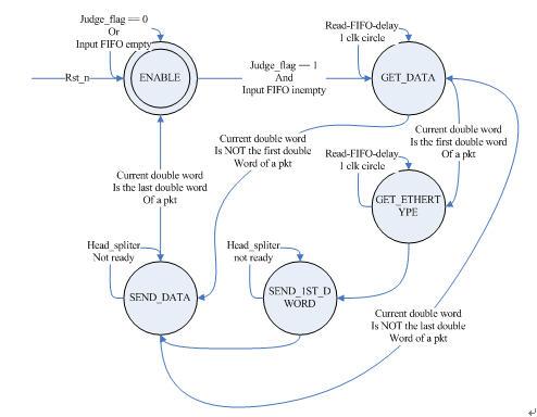
圖3.2-3:input arbiter狀態(tài)轉(zhuǎn)換圖
2、Control
① 子模塊列表
Sub module name | quantity | description |
Head_spliter | 2 | Split head and payload, send head to “head info extractor”, send payload to “FIFO ctrl payload” |
Head_info_extractor | 2 | Receive head from “head splitter”, extract “source number”, generate “generation number”. Store legacy head and packing info head respectively in “FIFO ctrl legacy” and “FIFO ctrl packinginfo” |
Control_arbiter | 1 | Detect ctrl bus to determine whether should process both channels synchronously or hold one channel and process the other. |
FIFO ctrl payload | 2 | Standard FIFO generated by CoreGen, store payload |
FIFO ctrl legacy | 2 | Standard FIFO generated by CoreGen, store legacy head |
FIFO ctrl packinginfo | 2 | Standard FIFO generated by CoreGen, store packing info head |
② 內(nèi)部結(jié)構(gòu)如圖3.2-4
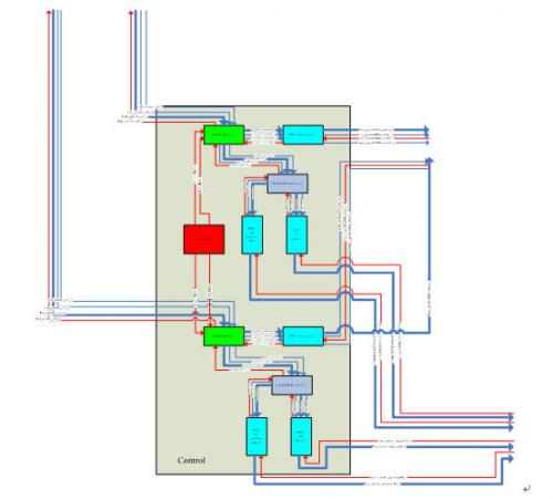
圖3.2-4:control模塊內(nèi)部結(jié)構(gòu)
③ 本模塊輸入輸出信號列表及說明
Signal name | Bit width | Input or output | description |
Data_arbiter_ctrl_1 | 64 | Input | Input data bus from “input arbiter 1” |
Ctrl_arbiter_ctrl_1 | 8 | Input | Input ctrl bus from “input arbiter 1” |
Val_arbiter_ctrl_1 | 1 | Input | 1=data from input arbiter 1 to head splitter 1 is valid, 0=otherwise |
Rdy_arbiter_ctrl_1 | 1 | output | 1=module “head splitter 1” is ready to receive from input arbiter 1, 0=otherwise |
Data_arbiter_ctrl_2 | 64 | Input | Input data bus from “input arbiter 2” |
Ctrl_arbiter_ctrl_2 | 8 | Input | Input ctrl bus from “input arbiter 2” |
Val_arbiter_ctrl_2 | 1 | Input | 1=data from input arbiter 2 to head splitter 2 is valid, 0=otherwise |
Rdy_arbiter_ctrl_2 | 1 | output | 1=module “head splitter 2” is ready to receive from input arbiter 2, 0=otherwise |
Data_payloadfifo_router_1 | 64 | output | output data bus to “payload router” |
Ctrl_payloadfifo_router_1 | 8 | output | Output ctrl bus to “payload router” |
Rd_en_payloadfifo_router_1 | 1 | Input | Read enable |
Empty_payloadfifo_router_1 | 1 | output | 1=FIFO ctil payload 1 is empty,0=otherwise |
Data_payloadfifo_router_2 | 64 | output | output data bus to “payload router” |
Ctrl_payloadfifo_router_2 | 8 | output | Output ctrl bus to “payload router” |
Rd_en_payloadfifo_router_2 | 1 | Input | Read enable |
Empty_payloadfifo_router_2 | 1 | output | 1=FIFO ctrl payload 2 is empty,0=otherwise |
Data_center_legacyfifo_1 | 64 | Output | Output data bus to “packing center” |
Rd_en_center_legacyfifo_1 | 1 | Input | Read enable |
Data_center_packingfifo_1 | 14 | Output | Output data bus to “packing center” |
Rd_en_center_packingfifo_1 | 1 | input | Read enable |
Data_center_legacyfifo_2 | 64 | Output | Output data bus to “packing center” |
Rd_en_center_legacyfifo_2 | 1 | Input | Read enable |
Data_center_packingfifo_2 | 14 | Output | Output data bus to “packing center” |
Rd_en_center_packingfifo_2 | 1 | input | Read enable |
clk | 1 | input | System clock, running at 125MHz |
Rst_n | 1 | input | System asynchronous reset signal |
④ 功能描述及數(shù)據(jù)流
本模塊為主控制模塊。子模塊control arbiter通過監(jiān)控兩條輸入通道的ctrl bus,控制子模塊head_spliter的兩個獨立的例化。具體控制操作如下:
若兩條輸入通道同時進來新的IP包,則同時處理兩條通道。
若輸入通道1進來新IP包時,通道2中IP包已經(jīng)在處理中,則阻塞通道1,直至通道2處理完畢再重新判決。
若同時處理兩條通道時,兩條通道中的數(shù)據(jù)包深度相同,則無需“PADDING”操作。若通道1中數(shù)據(jù)包發(fā)送完畢時(ctrl bus用one-hot-code標(biāo)明結(jié)尾字節(jié)),通道2中數(shù)據(jù)包尚未發(fā)送完畢,則需對通道1中數(shù)據(jù)包補零,并在ctrl bus中用0b11110000標(biāo)明此為padding數(shù)據(jù)。
子模塊head_spliter分離包頭和負載,并分別發(fā)往head_info_extractor提取封裝信息和FIFO_ctrl_payload暫存負載。
子模塊head_info_extractor提取包頭中的源IP地址,并由此生成4-bit信源編號(source number)和10-bit代編號(generation number),將生成的封裝信息存入FIFO_ctrl_packinginfo,將原始包頭存入FIFO_ctrl_legacy。
⑤ 關(guān)鍵時序及狀態(tài)機
Head_spliter狀態(tài)機如圖3.2-5
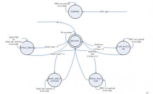
圖3.2-5:Head_spliter狀態(tài)機
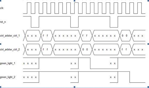
Control arbiter時序圖

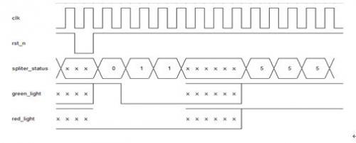
Head spliter時序圖
3、Coding
① 子模塊列表
Submodule name | quantity | description |
Payload router | 1 | Determine by the arrival of packets from both channels, whether should process coding or transport directly to packing module |
M64×8 multiplier | 2 | Multiply 64-bit data from “payload router” by 8-bit random number from “prng tap16” |
Prng tap16 | 1 | 8-bit random number generator |
M72×72 adder | 1 | 72-bit by 72-bit full adder |
M72to64 converter | 1 | Convert data bus width from 72-bit to 64-bit |
② Coding模塊的內(nèi)部結(jié)構(gòu)如圖3.2-6
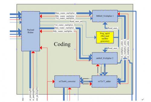
圖3.2-6:coding模塊內(nèi)部結(jié)構(gòu)
③ 本模塊輸入輸出信號列表及說明
Signal name | Bit width | I/O | description |
Data_payloadfifo_router_1 | 64 | Input | Input data bus from “FIFO ctrl payload 1” |
Ctrl_payloadfifo_router_1 | 8 | Input | Input ctrl bus from “FIFO ctrl payload 1” |
empty_payloadfifo_router_1 | 1 | Input | 1=FIFO ctrl payload 1 is empty,0=otherwise |
Rd_en_payloadfifo_rouer_1 | 1 | output | Read enable |
Data_payloadfifo_router_2 | 64 | Input | Input data bus from “FIFO ctrl payload 2” |
Ctrl_payloadfifo_router_2 | 8 | Input | Input ctrl bus from “FIFO ctrl payload 2” |
empty_payloadfifo_router_2 | 1 | Input | 1=FIFO ctrl payload 2 is empty,0=otherwise |
Rd_en_payloadfifo_rouer_2 | 1 | output | Read enable |
Router status | 3 | output | Output FSM state signal to “packing FIFO” and “packing center”, coordinate with the control of packing procedure |
Data_router_packingfifo | 73 | output | Output data bus to “packing FIFO”. Bit 64 is set to “0” to indicate this is an uncoded packet |
Wr_en_router_packingfifo | 1 | output | Write enable |
Rdy_router_packingfifo | 1 | input | 1=module “packing FIFO” is ready to receive from payload router, 0=otherwise |
Empty_packingfifo | 1 | input | 1=FIFO packing is empty,0=otherwise |
Data_converter_packingfifo | 73 | output | Output data bus to “packing FIFO”. Bit 64 is set to “1” to indicate this is a coded packet |
Wr_en_converter_packingfifo | 1 | Output | Write enable |
Rdy_converter_packingfifo | 1 | output | 1=module “packing FIFO” is ready to receive from m72to64 converter, 0=otherwise |
Empty_converterfifo | 1 | output | 1=FIFO converter is empty,0=otherwise |
Rand_num_1 | 8 | output | Output random number 1 to “packing center” |
Rand_num_2 | 8 | output | Output random number 2 to “packing center” |
clk | 1 | input | System clock running at 125MHz |
Rst_n | 1 | input | System asynchronous reset signal |
④ 功能描述及數(shù)據(jù)流
本模塊為主運算模塊。子模塊paylaod router構(gòu)建與上游模塊control的接口,從control的子模塊FIFO ctrl payload中讀取數(shù)據(jù)。若兩FIFO都非空,則說明control模塊同時處理了兩條通道,也即需要進行編碼操作。Paylpad router同時讀取兩個FIFO中的數(shù)據(jù),送往由m64×8 multiplier、m72×72 adder以及m72to64 converter組成的“編碼流水線”進行編碼運算,并向下游packing模塊發(fā)送編碼過的數(shù)據(jù)包。
子模塊prng tap16是8位偽隨機數(shù)產(chǎn)生器。使能信號rand_num_en有效時,產(chǎn)生一個8位偽隨機數(shù)。子模塊m64×8 multiplier是64乘8位乘法器,該模塊將負載與隨即系數(shù)相乘,得到72位結(jié)果。m72×72 adder是72位全加器,將兩個乘法器得到的結(jié)果相加得到編碼輸出。m72to64 converter是位寬轉(zhuǎn)換器,由于coding模塊輸出的數(shù)據(jù)總線仍需保持64位,所以需要該轉(zhuǎn)換器將72位編碼輸出轉(zhuǎn)換為64為編碼數(shù)據(jù)。由于是同步電路,采用同一時鐘,該位寬轉(zhuǎn)換將產(chǎn)生一定的數(shù)據(jù)囤積,需要較大緩存。
⑤ 關(guān)鍵時序與狀態(tài)機
- Payload router狀態(tài)機
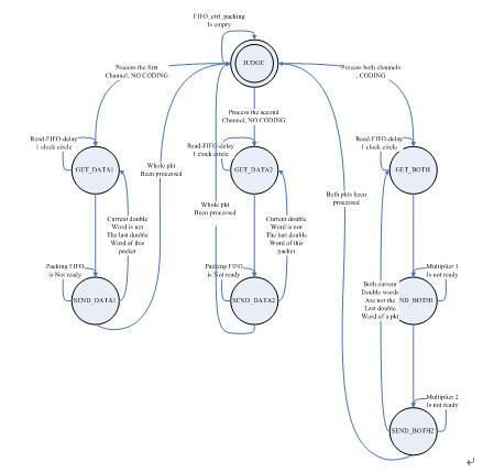
圖3.2-7 Payload router狀態(tài)機


評論