基于網絡編碼的多信源組播通信系統,包括源代碼,原理圖等 (三)

4、Packing
① 子模塊列表
Sub module name | quantity | Description |
Packing FIFO | 1 | Receive and store processed packets before being packed in “packing center” |
Packing center | 1 | Packing payload with all sorts of heads |
② 內部結構圖
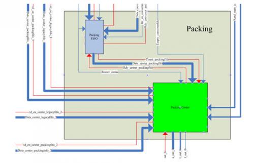
圖3.2-8 Packing內部結構圖
③ 本模塊輸入輸出信號列表及說明
Signal name | Bit width | I/O | Description |
Data_router_packingfifo | 73 | input | Input data bus from “payload router”. Bit 64 is set to “0” to indicate this is an uncoded packet |
Wr_en_router_packingfifo | 1 | Input | Write enable |
Rdy_router_packingfifo | 1 | Output | 1=module “packing FIFO” is ready to receive from payload router, 0=otherwise |
Router_status | 3 | input | Input FSM state signal to coordinate with the control of “packing FIFO” |
Empty_packingfifo | 1 | output | 1=FIFO packing is empty,0=otherwise |
Data_converter_packingfifo | 73 | input | Input data bus from “m72to64 converter”. Bit 64 is set to “1” to indicate this is a coded packet |
Wr_en_converter_packingfifo | 1 | Input | Write enable |
Rdy_converter_packingfifo | 1 | Output | 1=module “packing FIFO” is ready to receive from m72to64 converter, 0=otherwise |
Empty_converterfifo | 1 | Input | 1=FIFO converter is empty,0=otherwise |
Data_center_legacyfifo_1 | 64 | Input | Input data bus from “FIFO ctrl legacy 1” |
Rd_en_center_legacyfifo_1 | 1 | output | Read enable |
Data_center_packinginfo_1 | 14 | Input | Input data bus from “FIFO ctrl packinginfo 1” |
Rd_en_center_packinginfo_1 | 1 | output | Read enable |
Data_center_legacyfifo_2 | 64 | Input | Input data bus from “FIFO ctrl legacy 2” |
Rd_en_center_legacyfifo_2 | 1 | output | Read enable |
Data_center_packinginfo_2 | 14 | Input | Input data bus from “FIFO ctrl packinginfo 2” |
Rd_en_center_packinginfo_2 | 1 | output | Read enable |
Rand_num_center_1 | 8 | input | Input random number from “m64×64 multiplier 1” |
Rand_num_center_2 | 8 | input | Input random number from “m64×64 multiplier 2” |
Out_data_out_0 | 64 | output | Output data bus to “output arbiter” |
Out_ctrl_out_0 | 8 | Output | Output ctrl bus to “output arbiter” |
Data_val_out_0 | 1 | Output | 1=data from packing center to output arbiter is valid, 0=otherwise |
Rdy_out_0 | 1 | Input | 1=output arbiter is ready to receive from packing center, 0=otherwise |
clk | 1 | Input | System clock running at 125 MHz |
Rst_n | 1 | input | System asynchronous reset signal |
④ 功能描述及數據流
本模塊為封裝模塊。子模塊packing FIFO構建與coding模塊的數據接口,將接收并緩存編碼數據包以及未編碼數據包(使用額外第64位數據標志該包是否編碼,該位為“1”說明編碼,該位為“0”說明未編碼)。
子模塊packing center是主封裝模塊。它根據packing FIFO中讀出的數據判斷需要哪些包頭信息,然后向control模塊中相應FIFO讀取需要的包頭信息,并依次封裝成NCP數據包,發送到output arbiter。
⑤ 關鍵時序及狀態機
Packing center狀態機
第一層狀態機:packing_center_status
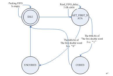
圖3 .2-9 packing_center_status狀態機
第二層狀態機:
coded_process
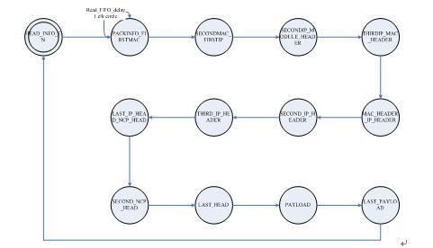
圖3 .2-10coded_process狀態機
uncoded_process
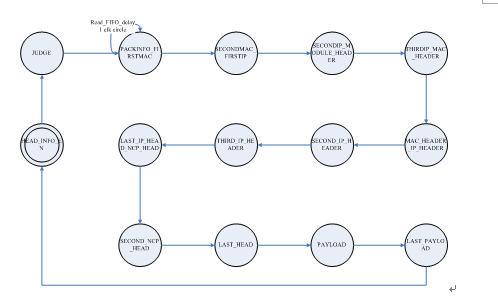
圖3.2-11 uncoded_process 狀態機
5、Output arbiter
① 本模塊輸入輸出信號列表及說明
Signal name | Bit width | Input or output | Description |
Out_data_out_0 | 64 | input | input data bus from “packing center” |
Out_ctrl_out_0 | 8 | Input | input ctrl bus from “packing center” |
Data_val_out_0 | 1 | Input | 1=data from packing center to output arbiter is valid, 0=otherwise |
Rdy_out_0 | 1 | output | 1=output arbiter is ready to receive from packing center, 0=otherwise |
Out_data_out_1 | 64 | input | input data bus from “input arbiter 1” |
Out_ctrl_out_1 | 8 | Input | input ctrl bus from “input arbiter 1” |
Data_val_out_1 | 1 | Input | 1=data from input arbiter 1 to output arbiter is valid, 0=otherwise |
Rdy_out_1 | 1 | output | 1=output arbiter is ready to receive from input arbiter 1, 0=otherwise |
Out_data_out_2 | 64 | input | input data bus from “input arbiter 2” |
Out_ctrl_out_2 | 8 | Input | input ctrl bus from “input arbiter 2” |
Data_val_out_2 | 1 | Input | 1=data from input arbiter 2 to output arbiter is valid, 0=otherwise |
Rdy_out_2 | 1 | output | 1=output arbiter is ready to receive from input arbiter 2, 0=otherwise |
Out_data_mac | 64 | output | output data bus to “MAC Layer” |
Out_ctrl_mac | 8 | Output | output ctrl bus to “MAC Layer” |
Data_val_mac | 1 | Output | 1=data from output arbiter to MAC layer is valid, 0=otherwise |
Rdy_mac | 1 | Input | 1=MAC layer is ready to receive from output arbiter, 0=otherwise |
clk | 1 | Input | System clock running at 125MHz |
Rst_n | 1 | input | System asynchronous reset signal |
② 功能描述及數據流
本模塊為輸出仲裁模塊。為協調多路輸出通道,避免沖突而設計。入端構建與input arbiter通信的兩路端口和與packing通信的一路端口,出端構建與MAC層通信的輸出端口。將選通并維護唯一一條輸入通道直至該數據包全部發送完畢。采用輪詢方式檢查三路輸入通道以避免沖突。
③ 關鍵時序及狀態機
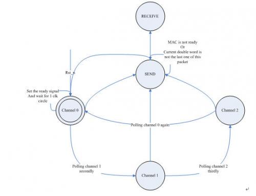
圖3.2-12 Output arbiter狀態機
3.3 轉發路由器詳細設計方案
3.3.1轉發路由器系統整體模塊圖
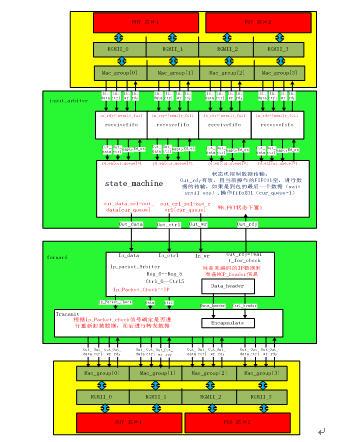
圖3.3-1總體模塊圖
系統模塊功能說明:該模塊有兩個子模塊input_arbiter模塊和forward模塊構成,其中前者為標準模塊;后者為自定義模塊,接受來自MAC層的數據包,經過相關處理輸出數據包,實現將未編碼的IP數據包封裝成NCP數據包并進行轉發以及將其它非IP數據包或NCP數據包進行直接轉發的功能。
3.3.2系統中各單元模塊的功能與時序
Input_arbiter模塊
① Input_arbiter模塊的內部結構圖如圖3.3-2
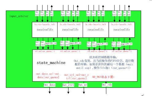
圖3.3-2 input_arbiter模塊
② 本模塊的輸入輸出信號列表及說明(如下例)
信號名稱 | 位寬 bits | I/O | 描述 |
in_data_n(n:0、1、2、3) | 64 | input | 從MAC層輸入的data數據 |
in_ctrl_n(n:0、1、2、3) | 8 | input | 從MAC層輸入的ctrlbus數據 |
in_wr_n(n:0、1、2、3) | 1 | input | 從MAC層輸入的數據寫使能信號(1為有效) |
in_rdy_n(n:0、1、2、3) | 1 | output | 輸出至MAC層的準備信號(1為準備完畢,可以寫入) |
out_data | 64 | output | 輸出至forward模塊的data數據 |
out_ctrl | 8 | output | 輸出至froward模塊的ctrl數據 |
out_wr | 1 | output | 輸出至forward模塊的寫使能信號(1為寫使能有效) |
out_rdy | 1 | input | 從forward模塊輸入的準備信號(1為準備好,可以寫入) |
本模塊的功能描述以及內部數據處理的過程
功能描述:從MAC層的接口傳來的數據信號寫入到receivefifo中,每個接口接一個fifo,通過本模塊的仲裁,循環查詢每個fifo,如果每個fifo不為空則輸出該fifo的數據到forward 模塊。本次實驗只用到接口1,其他接口實際上是沒有數據輸入,然而為了以后的可拓展設計,采取循環查詢每個fifo,這樣可以從每個接口進行數據讀入數據,更合理。
④ 關鍵時序和狀態機轉化圖
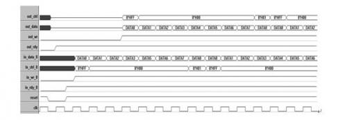
圖3.3-3 input_arbiter時序圖
2、forward模塊
① forward模塊的內部結構圖如圖3.3-4
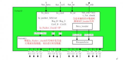
圖3.3-4
②本模塊的輸入輸出信號列表及說明(如下例)
信號名稱 | 位寬 bits | I/O | 描述 |
out_data | 64 | input | 從input_arbiter模塊輸出的data數據 |
out_ctrl | 8 | input | 從input_arbiter模塊輸出的ctrl數據 |
out_wr | 1 | input | 從input_arbiter模塊輸出的寫使能信號(1為寫使能有效) |
out_rdy | 1 | input | 輸出至input_arbiter模塊的準備使能信號(1為準備使能有效) |
out_data_n(n:0、1、2、3) | 64 | output | 輸出至MAC層的data數據 |
out_ctrl_n(n:0、1、2、3) | 8 | output | 輸出至MAC層的ctrlbus數據 |
out_wr_n(n:0、1、2、3) | 1 | output | 輸出至MAC層的數據寫使能信號(1為有效) |
out_rdy_n(n:0、1、2、3) | 1 | intput | 從MAC層輸入的準備信號(1為準備完畢,可以寫入) |
③ 本模塊的功能描述以及內部數據處理的過程
(1)Forward模塊下子模塊Ip_Packet_Arbiter 定義6個寄存器變量分別為:Reg_0—Reg_5 寬度為64bit, 6個寄存器變量:Ctrl_0—Ctrl_5寬度為8bit.分別存儲數據包的前48個字節數據和CtrlBus信息。以便對包頭進行解析,并進行判斷所屬的類型。
(2)判斷屬于哪一類型的數據包,如果是非IP數據包則從Ip_packet_Arbiter模塊發送一個信號Ip_Packet_Check的信號到Transmit模塊,通過data信號線和ctrl信號線將數據傳送到Transmit模塊并轉發到各個接口;
(3)如果屬于iP數據包則進一步判斷是屬于編碼后的數據包還是未編碼的數據包,如果是編碼后的數據包則和①做同樣處理,如果是未編碼的數據包,則進行相應的處理(更改modulheader、MAC的目標地址、Ip包頭、添加NCP包頭操作),然后將組合好的數據包頭和Ctrlbus 和Ip_Packet_Check信號一起送到Transmit模塊。在Transmit模塊通過收到的Ip_Packet_Check信號進行判斷是否需要對存放數據進行重新的封裝并進行相應處理,然后進行轉發操作。整個過程的流程圖如圖3.3-5
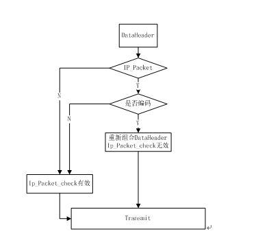
圖3.3-5
④關鍵時序和狀態機轉化圖
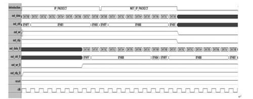
圖3.3-6
⑤ froward模塊下子模塊Transmit的狀態機以及描述如圖3.3-7
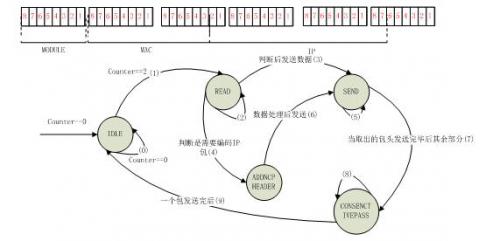
圖3.3-7
對整個狀態機工作條件進行詳細的描述如下:
當滿足滿足計數器counter=0的條件時,進入IDLE狀態;counter計數器不改變并且不是包頭的起始信號時則保持在該狀態;如果counter=1,發現包頭起始信號則保存該字段的值,并設置counter=2;
當滿足計數器counter=2時,并且是包的中間值信號時則跳轉到READ狀態;根據counter計數器的值有條件的保存在該狀態;counter自加;
當滿足計數器counter=3時,判斷MAC字段中上層協議的類型標志,如果為IP數據包繼續保持在READ狀態,counter+1;當counter=4時 進行判斷數據包中協議字段的如果為未編碼的IP數據包則保存在該狀態,counter+1;
當滿足counter=3時判斷上層協議類型標志為非IP數據包,則直接跳轉到SEND狀態;如果為已經編碼的IP數據包既NCP數據包,則調整到SEND狀態;
當counter=7的時候,跳轉到ADDNCPHEADER狀態;數據處理完畢后state=SEND;
當暫存的數據包沒有發送完之前則保持在該狀態;
當state=SEND時,跳轉到SEND狀態;
當暫存的數據包的字段發送完畢后,跳轉到CONSENCTIVEPASS(持續發包)狀態時;
判斷包尾的結束標志,如果不是包尾的結束標志則保持在該狀態;
判斷包尾的結束標志,如果是包尾的結束標志,則發最后一個字段,并跳轉到IDLE(起始狀態);


評論