使用寬帶電壓和電流反饋運(yùn)算放大器時(shí)的應(yīng)用基礎(chǔ)

Example B
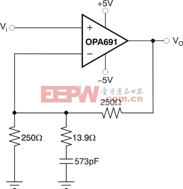
Where frequency response peaking is required, a CFB amplifier permits this characteristic to be achieved with reduced interaction between the gain shaping and the amplifier bandwidth.Figure 3shows an example single stage of a zero/pole pair using a high output current OPA691 CFB amplifier.
(Click to Enlarge Image)
Figure 3. Frequency response peaking circuit using the OPA691.
This example transitions from a gain of 2 V/V (6 dB) to a gain of +20 V/V (26 dB) over a 2 MHz to 20 MHz span. Implementing this design with a VFB requires a minimum gain bandwidth product (GBP) in excess of (20 × 20 MHz) = 400 MHz in order to not immediately roll off at the maximum gain setting.
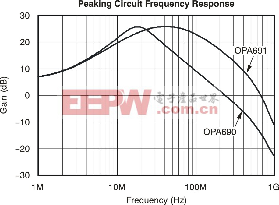
Figure 4shows this simulation where the improved performance of the CFB OPA691 is apparent.
(Click to Enlarge Image)
Figure 4. Peaking circuit frequency response with CFB (OPA691) and VFB (OPA690).
As a comparison, Figure 4 also shows the high output current OPA690 VFB; note that the 300 MHz GBP of the OPA690 is not quite enough for this application while the CFB OPA691 achieves the maximum 26 dB gain at 20 MHz and remains there up to an approximate -3 dB bandwidth of 100 MHz.
Example C
Sallen-Key, or voltage-controlled voltage source, active filters need a non-inverting gain amplifier that has a bandwidth far in excess of the desired filter bandwidth. While this type of filter can be implemented with VFB devices quite well, a CFB device would be preferred where higher frequency cutoff filters are needed, or where the amplifier gain needs to be flexible. The amplifier gain enters into the ideal filter transfer function as part of the Q setting equation. This gain also sets the low frequency gain in a low-pass filter design.
The local bandwidth of the op amp used in this design moves the actual filter poles away from the design targets. In the Sallen-Key low-pass filter, the actual poles move down and to the right in the complex s-plane. This shift gives an actual filter that has lower 0 and higher Q than targeted. To the extent that the amplifier bandwidth changes with gain setting, as it would with a VFB amplifier, the actual filter poles are impacted more strongly using a VFB over a range of gains in the design.
Using a CFB in this filter normally allows a more solid pole placement where the amplifier gain can be varied more


評論