數字儀表設計-高分辨率模擬數字轉換器應用

一、 前言:
本文引用地址:http://count.eepw.com.cn/count/doRedirect?http://www.104case.com/article/158817.htm在電子磅秤或溫度量測應用中,常會需要較高分辨率模擬到數字轉換器(Analog-to-Digital Converter;ADC)來量測模擬信號量化組件。而當提到高分辨率模擬到數字轉換器,都會聯想到ADI、Intersil、Maxim、Microchip、LTC、TI等國外大廠,但是這些國外的組件給人的印象就是單價高、交期長;對于工業控制及儀表的應用而言產品的單價,以模擬到數字轉換器占較多。隨著模擬集成電路成熟,各廠家分別生產架構為Σ-Δ或雙斜率的模擬到數字轉換器。以纮康科技為例,該公司所生產轉換器皆為Σ-Δ架構,有HY310x/HY311x系列Σ-Δ 24位高分辨率模擬數字轉換器、HY11Pxx系列具有高分辨率模擬數字轉換器的混合信號處理器(Mixed-Signal Microcontroller),及具有數字復用表模擬前端(Analog Front End)的專用芯片HY12P65。
本文將以HY3106為應用,它除為Σ-Δ 24位模擬到數字轉換器,并內建可程序放大器、溫度傳感器等外圍。
二、 HY310x功能簡介:
HY3106/HY3104/HY3102功能簡介:
1. 工作電壓范圍: 2.4V to 3.6V
2. 工作溫度范圍: -40℃ to +85℃
3. 內建VDDA穩壓器,可選擇Off, 2.4V, 2.7V, 3.0V或3.3V
4. 外部/內部頻率源
5. SPI 數據傳輸接口
6. 內置絕對溫度傳感器(±2℃)
7. SSOP16 封裝
8. 內建4種輸入模式切換(正向輸入、下短路、上短路、交錯)
9. 內建直流偏壓設置,可選擇0,±1/8,±1/4 , ±3/8, ±1/2,±5/8, ±3/4, ±7/8倍VREF的偏置電壓
10. 24位全差動輸入ΣΔADC模擬數字轉換器
u 極小的輸入噪聲50nVrms
u 數據輸出速率10, 80, 640或2560SPS
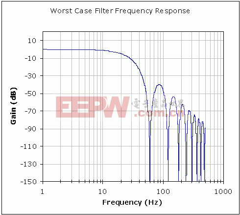
u 可抑制50/60Hz的訊號
u 在參考端內置高阻抗輸入緩沖器
11. 工作電流:
u 300μA @ gain=1, 2 or 4
u 950μA @ gain=64, 128
12. 低Sleep電流,約0.65μA(ENADC=0)
13. 內建前置放大器(PGA),可程序放大倍率x1, x2, x4, x8, x16, x32, x64, x128
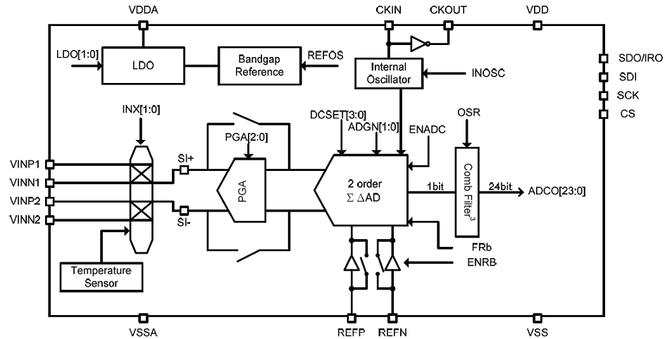
▲ HY310x內部功能方塊圖
三、 HY310x傳輸協議:
HY310x之SPI傳輸協議可分成兩種:
1. 單筆數據讀寫模式-在此模式,首先必須輸出Command,接下再寫入或讀取緩存器數據。
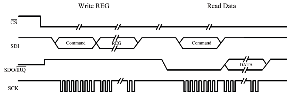
▲ Write Register and Read Register
2. 連續讀取模式-在此模式,首先必須輸出NCR(No Command for Read) Command,接下微控制等IRQ中斷信號,再讀取轉換數據緩存器。
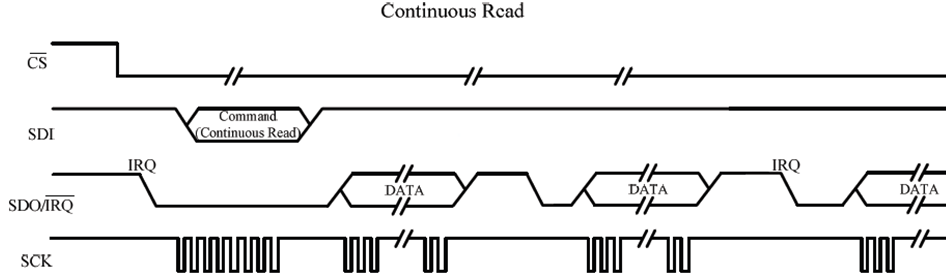
▲ Continuous read mode
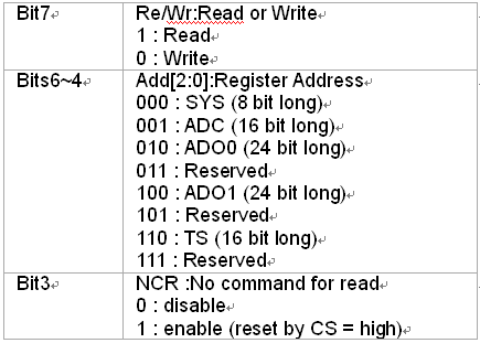
命令格式,分為讀寫控制、指定讀寫緩存器地址、NCR控制。
▼ SPI Command Format

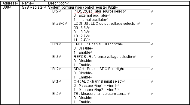
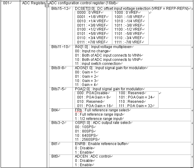
緩存器可分為設定及轉換數據緩存器。
▼ Register List(Setting)
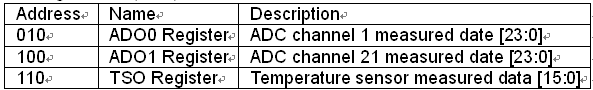
▼ Register List(Data)
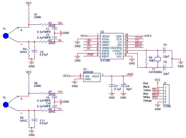
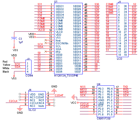
四、 電路圖:
????????? 五、 程序行表:
/*******************************************************************************
* main.c
* -----------------------------------------------------------------------------
* Copyright 2012 Hycon Technology, Corp.
* http://www.hycontek.com/
*
* Release 1.0
* 12/12/2012
*
* Program Description:
* --------------------
* C8051F330
* ---------
* | ------------------
* P0.7 | SCL (SMBus) ---> SCK | LCD Drive HY2613 |
* P0.6 | SDA (SMBus) ---> SDA ------------------
* P0.5 | RX0 (UART0) <---
* P0.4 | TX0 (UART0) --->
* | ------------------
* P0.3 | NSS (SPI0) ---> CS | |
* P0.2 | MOSI (SPI0) ---> SDI | Data Converters |
* P0.1 | MISO (SPI0) <--- SDO | HY3106 |
* P0.1 | SCK (SPI0) ---> SCK | |
* GND | ------------------
* |
* ---------
******************************************************************************/
//-----------------------------------------------------------------------------
// Includes
//-----------------------------------------------------------------------------
#include
#include
#include
#include
#include
//-----------------------------------------------------------------------------
// Global CONSTANTS
//-----------------------------------------------------------------------------
#define SYSCLK 24500000 // SYSCLK frequency in Hz
#define SPI_CLOCK 500000 // The SPI clock is a maximum of 500 kHz
#define SMB_FREQUENCY 10000 // Target SCL clock rate
// This example supports between 10kHz
// and 100kHz
#define WRITE 0x00 // SMBus WRITE command
#define READ 0x01 // SMBus READ command
// Status vector - top 4 bits only
#define SMB_MTSTA 0xE0 // (MT) start transmitted
#define SMB_MTDB 0xC0 // (MT) data byte transmitted
#define SMB_MRDB 0x80 // (MR) data byte received
// End status vector definition
//-----------------------------------------------------------------------------
// Global Variables
//-----------------------------------------------------------------------------
extern bit Sec1s_Flag; // 1Sec Flag
extern bit Sec20ms_Flag; // 20mSec Flag
extern bit ADC_Done_Flag; // Flag
extern unsigned char x20ms; // 設定1秒=50x20ms
extern unsigned char Delay_20ms;
unsigned long ADC0_Buffer;
unsigned long ADC1_Buffer;
unsigned long TS_Buffer;
unsigned char Tx_Data[25];
unsigned char TARGET; // Target SMBus slave address
bit SMB_BUSY; // Software flag to indicate when the
// SMB_Read() or SMB_Write() functions
// have claimed the SMBus
unsigned char SMB_RW; // Software flag to indicate the
// direction of the current transfer
unsigned long NUM_ERRORS; // Counter for the number of errors.
unsigned char NUM_BYTES_WR; // Number of bytes to write
// Master -> Slave
unsigned char Data_Buffer[18]={0};
sbit MISO = P0^1;
sbit MOSI = P0^2;
//-----------------------------------------------------------------------------
// Function PROTOTYPES
//-----------------------------------------------------------------------------
void System_Initial (void);
void HY3106_Initial(void);
void Read_ADC(void);
void Read_ADC1(void);
void Display (void);
void delay(void);
void ClearLCDframe(void);
void DisplayHYcon(void);
//-----------------------------------------------------------------------------
// MAIN Routine
//-----------------------------------------------------------------------------
void main (void)
{
System_Initial();
EA = 1; // Global enable 8051 interrupts
Ini_Display(); // Set and Clear LCD form
ClearLCDframe();
DisplayHYcon();
EA = 0; // Global disable 8051 interrupts
while(1);
HY3106_Initial();
delay();
EA = 1; // Global enable 8051 interrupts
Delay_20ms=25;
while(Delay_20ms!=0); // Wait 500mS
ADC_Done_Flag=0;
NSSMD0 = 0; // Step1: Activate Slave Select
Read_ADC();
//----------------------------------
// Main Application Loop
//----------------------------------
while (1) // Loop and wait for interrupts
{
if (Sec20ms_Flag == 1)
{
Display();
Sec20ms_Flag = 0;
}
if(MISO==0)
{
Read_ADC1();
ADC_Done_Flag=0;
Delay_20ms=5;
while(Delay_20ms!=0); // Wait 100mS
}
}
}
/*----------------------------------------------------------------------------*/
/* Clear LCD RAM Data */
/*----------------------------------------------------------------------------*/
void ClearLCDframe(void)
{
unsigned char Index=0;
for(Index=0;Index<18;Index++)
{
Data_Buffer[Index]=0x00;
}
RAM2LCD(Data_Buffer,18);
}
/*----------------------------------------------------------------------------*/
/* Inital the LCD Drive */
/*----------------------------------------------------------------------------*/
void Ini_Display(void)
{
Tx_Data[0] = ICSET|SWRst|OscModeInt; //ICSET equ 0EAh
Tx_Data[1] = DISCTL|PoMode3|FrInv|PoHigh; //DISCTL equ 0BFh
Tx_Data[2] = ADSET; //ADSET equ 000h
Tx_Data[3] = ADSET; //ADSET equ 000h
NUM_BYTES_WR=4;
TARGET = HY2613_Slave_addr; // Target the HY2613(0x7C) Slave for next
// SMBus transfer
while (SMB_BUSY); // Wait for SMBus to be free.
SMB_BUSY = 1; // Claim SMBus (set to busy)
SMB_RW = 0; // Mark this transfer as a WRITE
STA = 1; // Start transfer
while (SMB_BUSY); // Wait for transfer to complete
}
/*----------------------------------------------------------------------------*/
/* RAM Data Send to LCD */
/*----------------------------------------------------------------------------*/
void RAM2LCD(unsigned char *Buffer_Adr, unsigned char length)
{
Tx_Data[0] = DISCTL|PoMode3|FrInv|PoHigh; //
Tx_Data[1] = BLKCTL; //0xf0
Tx_Data[2] = PIXCTL; //0xfc
Tx_Data[3] = MODE_SET|Dis_ON; //0xc8
Tx_Data[4] = ADSET; //0x00
NUM_BYTES_WR=5;
for(;length>0;length--)
{
Tx_Data[NUM_BYTES_WR] = *Buffer_Adr++;
NUM_BYTES_WR++;
}
TARGET = HY2613_Slave_addr; // Target the HY2613(0x7C) Slave for next
// SMBus transfer
while (SMB_BUSY); // Wait for SMBus to be free.
SMB_BUSY = 1; // Claim SMBus (set to busy)
SMB_RW = 0; // Mark this transfer as a WRITE
STA = 1; // Start transfer
while (SMB_BUSY); // Wait for transfer to complete
}
//-----------------------------------------------------------------------------
// Measure Analog Value
//-----------------------------------------------------------------------------
void Read_ADC(void)
{
unsigned char buffer;
// SPI Command
NSSMD0 = 0; // Step1: Activate Slave Select
Delay_20ms=25;
while(Delay_20ms!=0); // Wait 500mS
while(MISO==1);
buffer= Read_Reg|ADC0_Register|NCR;
SPI0DAT =buffer; // Step2: Send command
while (!SPIF); // Step3: Wait for end of transfer
SPIF = 0; // Step4: Clear the SPI intr. flag
SPI0DAT = 0xFF; // Dummy write to output serial clock
while (!SPIF); // Wait for the value to be read
SPIF = 0;
SPI0DAT = 0xFF; // Dummy write to output serial clock
while (!SPIF); // Wait for the value to be read
SPIF = 0;
SPI0DAT = 0xFF; // Dummy write to output serial clock
while (!SPIF); // Wait for the value to be read
SPIF = 0;
delay();
}
//-----------------------------------------------------------------------------
// Measure Analog Value
//-----------------------------------------------------------------------------
void Read_ADC1(void)
{
unsigned char buffer;
// SPI Command
NSSMD0 = 0; // Step1: Activate Slave Select
SPI0DAT = 0xFF; // Dummy write to output serial clock
while (!SPIF); // Wait for the value to be read
SPIF = 0;
buffer =SPI0DAT;
ADC0_Buffer=buffer;
SPI0DAT = 0xFF; // Dummy write to output serial clock
while (!SPIF); // Wait for the value to be read
SPIF = 0;
buffer =SPI0DAT;
ADC0_Buffer=(ADC0_Buffer<<8)+buffer;
SPI0DAT = 0xFF; // Dummy write to output serial clock
while (!SPIF); // Wait for the value to be read
SPIF = 0;
buffer =SPI0DAT;
ADC0_Buffer=(ADC0_Buffer<<8)+buffer;
delay();
}
//-----------------------------------------------------------------------------
// HY3106 Initialization
//-----------------------------------------------------------------------------
void HY3106_Initial(void)
{
unsigned char buffer;
//-----------------------------------------------------------------------------
// SPI Command
NSSMD0 = 0; // Step1: Activate Slave Select
buffer= Write_Reg|SYS_Register;
SPI0DAT =buffer; // Step2: Send command
while (!SPIF); // Step3: Wait for end of transfer
SPIF = 0; // Step4: Clear the SPI intr. flag
//System Configuration Setting
buffer= INOSC|LDO_2V4|ENLDO|REFOS|SDOH|CH1;
SPI0DAT =buffer; // Step2: Send command
while (!SPIF); // Step3: Wait for end of transfer
SPIF = 0; // Step4: Clear the SPI intr. flag
NSSMD0 = 1; // Step5: Deactivate Slave Select
delay();
//-----------------------------------------------------------------------------
// SPI Command
NSSMD0 = 0; // Step1: Activate Slave Select
buffer= Read_Reg|SYS_Register;
SPI0DAT =buffer; // Step2: Send command
while (!SPIF); // Step3: Wait for end of transfer
SPIF = 0; // Step4: Clear the SPI intr. flag
SPI0DAT = 0xFF; // Dummy write to output serial clock
while (!SPIF); // Wait for the value to be read
SPIF = 0;
Data_Buffer[0] =SPI0DAT;
NSSMD0 = 1; // Step5: Deactivate Slave Select
delay();
//-----------------------------------------------------------------------------
// SPI Command
NSSMD0 = 0; // Step1: Activate Slave Select
buffer= Write_Reg|ADC_Register;
SPI0DAT =buffer; // Step2: Send command
while (!SPIF); // Step3: Wait for end of transfer
SPIF = 0; // Step4: Clear the SPI intr. flag
//ADC Control Register Setting 1
buffer = DCSET0|INX0|ADGN1;
SPI0DAT =buffer; // Step2: Send command
while (!SPIF); // Step3: Wait for end of transfer
SPIF = 0; // Step4: Clear the SPI intr. flag
//ADC Control Register Setting 2
buffer = PGA1|FRb0|OSR_10|ADCEN;
SPI0DAT =buffer; // Step2: Send command
while (!SPIF); // Step3: Wait for end of transfer
SPIF = 0; // Step4: Clear the SPI intr. flag
NSSMD0 = 1; // Step5: Deactivate Slave Select
delay();
//-----------------------------------------------------------------------------
// SPI Command
NSSMD0 = 0; // Step1: Activate Slave Select
buffer= Read_Reg|ADC_Register;
SPI0DAT =buffer; // Step2: Send command
while (!SPIF); // Step3: Wait for end of transfer
SPIF = 0; // Step4: Clear the SPI intr. flag
SPI0DAT = 0xFF; // Dummy write to output serial clock
while (!SPIF); // Wait for the value to be read
SPIF = 0;
Data_Buffer[1] = SPI0DAT;
SPI0DAT = 0xFF; // Dummy write to output serial clock
while (!SPIF); // Wait for the value to be read
SPIF = 0;
Data_Buffer[2] = SPI0DAT;
NSSMD0 = 1; // Step5: Deactivate Slave Select
delay();
}
//-----------------------------------------------------------------------------
// Display Digits Application Code
// Update the LCD Display
//-----------------------------------------------------------------------------
void Display(void)
{
char LCD_ADDR;
unsigned long buffer;
buffer=ADC0_Buffer/3.4;
for(LCD_ADDR=2;LCD_ADDR<8;LCD_ADDR++)
{
Data_Buffer[LCD_ADDR] = seg[buffer % 10];
buffer = buffer / 10;
}
RAM2LCD(Data_Buffer,18);
}
/*----------------------------------------------------------------------------*/
/* Display HYcon Char */
/*----------------------------------------------------------------------------*/
void DisplayHYcon(void)
{
Data_Buffer[2]=0x00;
Data_Buffer[3]=Char_H;
Data_Buffer[4]=Char_Y;
Data_Buffer[5]=Char_c;
Data_Buffer[6]=Char_o;
Data_Buffer[7]=Char_n;
RAM2LCD(Data_Buffer,11);
}
//-----------------------------------------------------------------------------
// Peripheral specific initialization functions,
// Called from the Init_Device() function
//-----------------------------------------------------------------------------
void System_Initial()
{
//PCA_Init()
PCA0MD &= ~0x40; // WDTE = 0 (clear watchdog timer enable)
PCA0MD = 0x00;
// Oscillator_Init()
OSCICN = 0x83; // Internal H-F Oscillator Enabled.
// SYSCLK derived from Internal H-F Oscillator divided by 1.
// Init Timer2 to generate interrupts at a 50 Hz rate.
TMR2CN = 0x00; // Stop Timer2; Clear TF2; use SYSCLK/12 as timebase
CKCON &= ~0x60; // Timer2 clocked based on T2XCLK;
TMR2RL = -(SYSCLK / 12 / 50); // Init reload values
TMR2 = 0xffff; // set to reload immediately
ET2 = 1; // enable Timer2 interrupts
TR2 = 1; // start Timer2
// Configure Timer1 for use as SMBus clock source
#if ((SYSCLK/SMB_FREQUENCY/3) < 255)
#define SCALE 1
CKCON |= 0x08; // Timer1 clock source = SYSCLK
#elif ((SYSCLK/SMB_FREQUENCY/4/3) < 255)
#define SCALE 4
CKCON |= 0x01;
CKCON &= ~0x0A; // Timer1 clock source = SYSCLK / 4
#endif
TMOD = 0x20; // Timer1 in 8-bit auto-reload mode
// Timer1 configured to overflow at 1/3 the rate defined by SMB_FREQUENCY
TH1 = -(SYSCLK/SMB_FREQUENCY/SCALE/3);
TL1 = -(SYSCLK/SMB_FREQUENCY/SCALE/3); // Init Timer1
TR1 = 1; // Timer1 enabled
// Configure and enable SMBus
SMB0CF = 0x5D; // Use Timer1 overflows as SMBus clock
// source;
// Disable slave mode;
// Enable setup & hold time extensions;
// Enable SMBus Free timeout detect;
// Enable SCL low timeout detect;
SMB0CF |= 0x80; // Enable SMBus;
//EIE1 |= 0x01; // Enable the SMBus interrupt
//SPI_Init
SPI0CFG = 0x70; //MSTEN 1: Enable master mode. Operate as a master.
//CKPHA 1: Data centered on second edge of SCK period.
//CKPOL 1: SCK line high in idle state.
SPI0CN = 0x0D;
SPI0CKR = (SYSCLK/(2*SPI_CLOCK)); //SPI frequency 500kHz
//Port_IO_Init
P0MDOUT = 0x0D; // Make SCK, MOSI, and NSS push-pull
XBR0 = 0x07; // Enable UART on P0.4(TX) and P0.5(RX)
// Enable the SPI on the XBAR
// Enable the SMBus on the XBAR
XBR1 = 0x40; // Enable crossbar and enable weak pull-ups
//Ext_Interrupt_Init
TCON = 0x05; // /INT 0 and /INT 1 are edge triggered
IT01CF = 0x61; // /INT0 active low; /INT0 on P0.1;
// /INT1 active low; /INT1 on P0.6
//EX0 = 1; // Enable /INT0 interrupts
//EX1 = 1; // Enable /INT0 interrupts
PX0 = 1;
}
//-----------------------------------------------------------------------------
// SMBus Interrupt Service Routine (ISR)
//-----------------------------------------------------------------------------
INTERRUPT(SMBUS0_ISR, INTERRUPT_SMBUS0)
{
bit FAIL = 0; // Used by the ISR to flag failed transfers
static unsigned char sent_byte_counter;
// Normal operation
switch (SMB0CN & 0xF0) // Status vector
{
// Master Transmitter/Receiver: START condition transmitted.
case SMB_MTSTA:
SMB0DAT = TARGET|SMB_RW; // Load target address & R/W bit
STA = 0; // Manually clear START bit
sent_byte_counter = 1; // Reset the counter
break;
// Master Transmitter: Data byte transmitted
case SMB_MTDB:
if (ACK) // Slave ACK?
{
if (SMB_RW == WRITE) // If this transfer is a WRITE,
{
if (sent_byte_counter <= NUM_BYTES_WR)
{
// send data byte
SMB0DAT = Tx_Data[sent_byte_counter-1];
sent_byte_counter++;
}
else
{
STO = 1; // Set STO to terminate transfer
SMB_BUSY = 0; // And free SMBus interface
}
}
else {} // If this transfer is a READ,
// proceed with transfer without
// writing to SMB0DAT (switch to receive mode)
}
else // If slave NACK,
{
STO = 1; // Send STOP condition, followed
STA = 1; // By a START
NUM_ERRORS++; // Indicate error
}
break;
default:
FAIL = 1; // Indicate failed transfer
// and handle at end of ISR
break;
} // end switch
if (FAIL) // If the transfer failed,
{
SMB0CF &= ~0x80; // Reset communication
SMB0CF |= 0x80;
STA = 0;
STO = 0;
ACK = 0;
SMB_BUSY = 0; // Free SMBus
FAIL = 0;
NUM_ERRORS++; // Indicate an error occurred
}
SI = 0; // Clear interrupt flag
}
/*---------------------------------------------------------------------------*/
/* End Of File */
/*---------------------------------------------------------------------------*/
六、 芯片供貨商:
l 纮康科技(Hycon Technology)專注于溫度、壓力、重量、電壓、電流、功率……等模擬訊號的量測及監視。主要提供在電池管理、儀器儀表(包含醫療、計量、 溫度…),及工業控制等領域的相關芯片開發。

模擬信號相關文章:什么是模擬信號
adc相關文章:adc是什么
電路圖符號相關文章:電路圖符號大全


評論