EPOT應用:偏移調整的運算放大器電路-EPOT Appli

Electronic Potentiometers (EPOTS) offer designers the opportunity to control a resistance via a digital interface and can be used in place of mechanical potentiometers or DACs in some circuits. While each application circuit has it own specific nuances (sometimes changing with the times and technology), circuits that account for a DC offset often use the same basics. This article discusses various DC offset adjustment circuits for op amps and the advantages and disadvantages of each.
In some systems, a DC offset voltage at the inputs will contribute a significant error to the output. This is especially true in high gain configurations. An offset adjustment circuit can be added to "null" out the offset voltage, making high gain stages practical even with significant input offset voltages. Some op-amps offer internal offset adjustment via a dedicated pin; for these devices, the potentiometer is used in a straight-forward manner as discussed in the op-amp's data sheet. The following application circuits use external offset adjustment for op amps that do not feature dedicated offset adjustment pins.
Thevenin Equivalent Circuit
In several of the circuits presented, the EPOT is used as shown in Figure 1. Please refer to the application note "Finding the Thevenin Equivalent Circuit for an EPOT-Based Resistor Network" for a derivation of the equations. The circuit can be simplified by replacing the EPOT network with its Thevenin equivalent.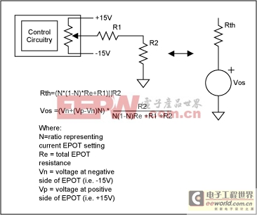
Figure 1. Thevenin equivalent of EPOT offset resistor network.
These equations can be further simplified with the assumptions that R2R1 and ReR1. With these assumptions,
Rth = ~R2, and
Vos = ~(Vn + (Vp-Vn)N) × (R2/R1).
The EPOT offset network can be viewed as a voltage source with a source impedance of R2. If the impedance Rth is an issue in a given op-amp configuration, it can be greatly reduced by using a voltage follower. For an example, take a look at the MAX4165, which has an output impedance of 0.1Ω. However, in most configurations, the impedance of Rth is negligible.
Basic Inverting Amplifier
The diagram in Figure 2 shows a simple way to add offset adjustment to the basic inverting configuration.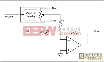
Figure 2. Basic inverting amp.
As this topology is effectively a summing amplifier configuration with the adjustment voltage input derived from the EPOT, the full range of available offset adjustment seen at the output is the injected current multiplied by the feedback resistor or ±Vos × (Rf/R1). With Rf = 10K and R1 = 4.7M, a current of ±3.2uA is obtained, resulting in an offset adjustment range of ±32mV. If a 32 tap EPOT is used, each step is approximately 2mV.
Another inverting configuration uses the non-inverting input to adjust the offset of the device, as shown in Figure 3.
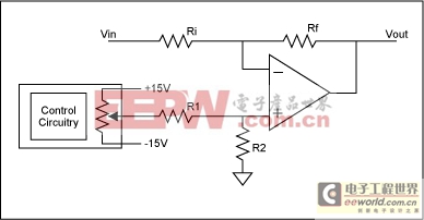
Figure 3. Inverting w/ offset on non-inverting input.
One advantage of this approach is that the offset resistor network is independent of the feedback network. As a result, this configuration is preferred in instances where the source impedance and input leakage currents require the use of very large values of Ri or Rf (i.e. very high gain circuits). In this circuit, the offset voltage added to the output is Vos(1+Rf/Ri) where Vos is the voltage at the non-inverting input of the op-amp. The full range of adjustment for Vos is ±15V × R2/(R1+R2). With R1=470kΩ and R2 set to 100Ω with a 50kΩ, 32 tap, EPOT, the full range of adjustment is ±3.2mW and each step is ~2mV. Using the Thevenin equivalent circuit of Figure 1, the voltage setting that correlates to a given EPOT setting can be determined. To determine the effect Rth has on the system, multiply it by the input current of the op-amp. In most cases, the number will be insignificant.
Non-Inverting Configurations
Figure 4 shows a non-inverting amplifier configuration using an EPOT for offset adjustment. Because the resistor Ri is not directly tied to ground, the equations for this circuit are fairly complex. By using the Thevenin replacement and a simplifying assumption, the analysis becomes much more straightforward.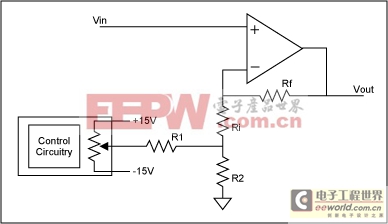
Figure 4. Non-inverting amplifier with EPOT for offset control.
The output voltage for this circuit is:
Vo = Vin(1+Rf/(Ri+Rth)) - Vos(Rf/(Ri+Rth))
From equation (1) we see that Rth = R2. And from equation (2), Vos = ~(Vn+ (Vp-Vn)N) × (R2/R1). Assuming R2Ri, then R2 can be ignored. Using the Thevenin equivalent network, the circuit simplifies to that shown in Figure 5.
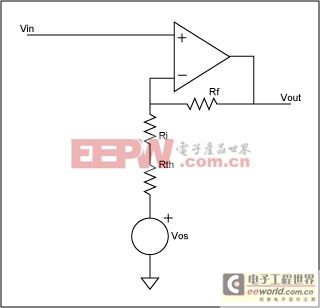
Figure 5. Non-inverting with offset voltage.
Non-Inverting Configuration for High Gains
An alternate non-inverting configuration is shown in Figure 6. A potential source of error for this circuit is that the amount of offset current being injected (i.e. the ratio of additional current IR1 to the current in Ri) changes with the amplitude of the input signal. This is because this configuration forces the inverting input to the amplifier to be the same as the input signal. As a result, this configuration is recommended for high gain systems where the change in voltage at the op amp's negative input terminal is relatively small, resulting in a small change in current IR1.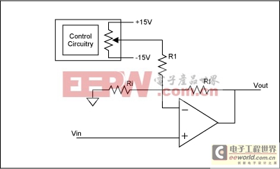
Figure 6. Alternate non-inverting amplifier configuration.
Differential Amplifier Configuration
Figure 7 shows a differential amplifier configured for offset adjustment. In the standard configuration, the resistor Rf' is connected directly to ground. If it is, instead, connected to an ideal voltage source, that voltage appears directly on the output as an offset.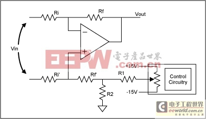
Figure 7. Differential amplifier.
The voltage across R2 is the offset voltage that will be directly added to the output of the circuit shown. If we treat R2 as a negligible impedance compared to Rf', the equation for the output becomes:
Vo = -Vin × (Rf/Ri) + Vos
Where Vos is the voltage across R2 and can be calculated using the Thevenin equivalent as shown in Figure 1.
In practical circuits, the equivalent source impedance added by the EPOT offset network adds an error to the gain of the system. This is easily illustrated by replacing the resistor network by its Thevenin equivalent:
Figure 8 shows how the equivalent impedance of Rth adds an imbalance. This can be compensated by adjusting Rf'. While there may still be some non-linearity due to Rth over the full range of the EPOT, in most cases, since Rth will be dominated by R2, these non-linearities are insignificant.
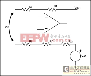
Figure 8. Differential amp with Thevenin equivalent of offset network.


評論