微電路具有自動關機和低電池鎖定功能-Micropowe

This micropower circuit provides shutdown, power-up, and low-battery lockout functions automatically, without the need for software or operator control (Figure 1). Featuring 2.3V hysteresis, the circuit eliminates the use of microprocessor I/O pins for charger detection, battery-threshold monitoring, and shutdown control. Under full load, the complete power-management circuit draws less than 200μA of supply current.
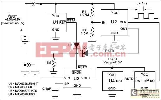
Figure 1. This micropower circuit provides shutdown, power-up, and low-battery lockout functions for this three-cell NiCd-based circuit without the need for software or operator control.
After the cutoff point for battery discharge is reached, the circuit locks out (disconnects) the battery from the load (Load1). This action prevents circuit "chatter" and deep discharge until the battery is in its charger cradle. A common and annoying problem with battery-voltage monitors, chatter is the circuit's response to fluctuations in battery-terminal voltage. These fluctuations take place when the recurring load connections toggle the battery between its discharge and relaxed-open-circuit conditions.
For a three-cell NiCd battery, the typical terminal voltage is 4.9V fully charged, 3.6V under load, and 2.5V at discharge. The load should be disconnected at 2.5V, but not reconnected, as the resulting terminal voltage (VBATT) floats to the open-circuit condition. The circuit in Figure 1 disconnects the load at 2.5V and reconnects it while the battery is in its charger cradle (4.68V).
An ultra-low-power microprocessor (μP)-reset device (U1) generates an active-low output (active-low RSTA) whenever VBATT equals 4.63V. The output of a micropower latching comparator (U2) causes active-low RSTB to transition low if VBATT is less than 2.5V. These outputs from U1 and U2 are ORed by diodes D1 and D2, generating a system-shutdown control (active-low RSTC). Figure 2 demonstrates the relationship between the various reset states and the battery-discharge profile.
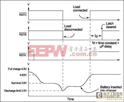
Figure 2. The response of the three reset signals in Figure 1 is shown over a typical discharge-charge cycle. The battery voltage profile is displayed in the bottom waveform.
When VBATT is less than 2.5V, active-low RSTC disconnects Load1 from the battery by shutting down U3. U3 is a low-noise low-dropout linear regulator in an SOT-23 package. It has a preset output of 2.5V, a maximum ground-pin current of 180μA (when supplying 150mA), and a supply current of only 10nA during shutdown.
If VBATT is greater than 4.63V, the circuit releases active-low RSTC. As a result, U3 comes out of shutdown and delivers power to the μP. Another μP supervisor (U4) holds the active-low RSTD signal low until the microprocessor's VCC exceeds 2.2V. Once active-low RSTD is released, the μP begins operating and clears U2 by pulsing its CLR input high for 1μs.
A similar version of this article appeared in the April 30, 2001 issue of Electronic Design.


評論