最大限度地延長(zhǎng)電池壽命,減少更換-Maximize Bat

Battery-powered portable and handheld devices with plug-in wall adapters must switch automatically between the battery and the wall source when the AC adapter is connected. A common way to do this is with a diode-OR connection. But the forward voltage drop of the diode, (0.6V to 0.7V) is a large percentage of the battery's terminal voltage, especially for devices that run from one- to three-cell battery packs. That's a significant amount of wasted power, shortening battery life. Using a Schottky diode (0.3V to 0.5V drop) improves matters somewhat, but a FET switch reduces the drop to less than 0.1V.
The circuit of Figure 1 switches between an external supply (a wall plug) and a battery pack consisting of two or three AA cells. The design extends useful battery life by minimizing loss in the FET switchover element (Q1). It also debounces the external supply. The FET shown was selected for its low RDS(ON) and low VGS, which is specified down to 1.8V. Thus, the FET can respond to a nearly discharged battery pack of two AA cells (0.9V each).
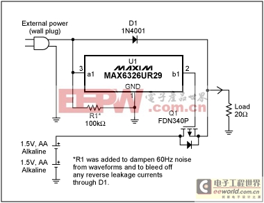
Figure 1. This circuit provides battery/wall-source switchover while debouncing the wall-source output. The low RDS(ON) of Q1 reduces its voltage drop to less than 0.1V.
Microprocessor-supervisory circuit U1 acts as a wall-source detector and debouncer. It monitors the wall supply, and its built-in delay ensures that it will switch from battery power to the wall supply only when the wall supply is stable, and at or above U1's trip voltage.
The battery will be back-driven (charged) during this delay period of typically 185ms. Note the effect on load voltage when switching from the battery to the wall supply (Figure 2), and vice versa (Figure 3).
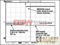
Figure 2. A 20Ω load in Figure 1 (bottom trace) registers a slight mismatch as the wall supply takes over from the battery, indicated by the change in U1's output (top trace).
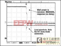
Figure 3. As wall power is removed in Figure 1 (indicated by U1's response in the top trace), the load response shows the effect of a voltage drop across Q1's body diode (bottom trace).
The push-pull, active-low output of U1 drives Q1's gate directly, without external components. If U1's time-out delay is too long, consider the pin compatible MAX6801 (SOT23 package) or MAX6381 (SC70 package), which offer delay options of 1ms, 20ms, and higher. Another pin-compatible option is the MAX6375 voltage detector (SC70 package). It provides no time-out delay, but incurs minimal back-drive effects on the battery.
Note that Q1 is reverse-connected with its drain to the battery and its source to the load. This allows its internal body diode to provide the initial current path to the load. At the same time it blocks the wall supply from uncontrolled charging (backdriving) of the AA cells when Q1 is turned off.
A similar version of this article appeared in the May 13, 2002 issue of Electronic Design magazine.


評(píng)論