基于FPGA的數字秒表設計與仿真

when “0101”=>dataoutput=“0100100”;
when “0110”=>dataoutput=“0100000”;
when “0111”=>dataoutput=“0001111”;
when “1000”=>dataoutput=“0000000”;
when “1001”=>dataoutput=“0000100”;
when others=>dataoutput=“1111111”;
end case;
end process;
3 功能驗證以及下載實現
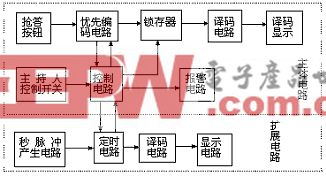
完成以上各個子模塊的設計后,該數字秒表的模塊設計就基本完成了,剩下的工作就是通過一個頂層文件將各個子模塊連接起來。在頂層文件中可以將以上各個子模塊看作一個個黑匣子,只將其輸入輸出端對應相連就可以了。下面是該頂層文件的VHDL源程序:
architecture Behavioral of topfile is
signal clk:std_logic:='0';
signal enableout:std_logic:='0';
signal data0,data1,data2,
data3,data4,data5:std_logic_vector(3
downto 0):=“0000”;
component abc
port(clk:in std_logic;
dout:out std_logic);
end component;
component enable
port(enablein:in std_logic;
enableout:out std_logic);
end component;
component highlevel
port(rst,clk,clear:in std_logic;
output1,output2,output3,
output4,output5,output6:out
std_logic_vector(3 downto 0);
carryout:out std_logic);
end component;
component yima
port(datainput:in std_logic_vector(3 downto 0);
dataoutput: out std_logic_vector(6 downto 0));
end component;
begin
u0:abc port map(clkin,clk);
u1:enable port map(enablein,enableout);
u2:highlevel port map(enableout,clk,clear,data0,data1,data2,data3,data4,data5);
u3:yima port map(data0,dataout0);
u4:yima port map(data1,dataout1);
u5:yima port map(data2,dataout2);
u6:yima port map(data3,dataout3);
u7:yima port map(data4,dataout4);
u8:yima port map(data5,dataout5);
end Behavioral;
由于各個子模塊都已經經過驗證無誤,并且頂層文件中不涉及復雜的時序關系,相當于只是將各個模塊用導線連接起來,只要各個端口的連接對應正確即可,所以不需寫專門的test bench進行驗證。完成以上設計后,即可進行邏輯綜合,綜合無誤后進行管腳適配,生成。bit文件然后下載到實驗板上測試。經過反復多次測試,以上設計完全滿足了預期的設計指標,開始/停止按鍵和清零按鍵都能準確的控制秒表的運行,七段顯示數碼管也能夠準確的顯示計時結果。通過與標準秒表對比,該設計的計時誤差在0.03s以內,而這其中也包括實驗板上晶振由于長期使用所帶來的誤差。
4 結束語
本文所介紹數字秒表設計方法,采用了當下最流行的EDA設計手段。在Xinlinx FPGA開發環境下,采用至上而下的模塊化設計方法,使得系統開發速度快、成本低、系統性能大幅度提升。通過實驗驗證,本文設計的數字秒表計時準確、性能穩定,可以很容易嵌入其他復雜的數字系統,充當計時模塊。
利用EDA設計工具,結合基于FPGA的可編程實驗板,輕松實現電子芯片的設計,現場觀察實驗結果,大大縮短了產品的設計周期和調試周期,提高了設計的可靠性和成功率,體現了邏輯器件在數字設計中優越性。


評論