DIY自動(dòng)售貨機(jī)——基于Arduino的機(jī)電一體化項(xiàng)目

在這個(gè)項(xiàng)目中,我們將學(xué)習(xí)如何制作基于Arduino的DIY自動(dòng)售貨機(jī)。我將向您展示構(gòu)建它的整個(gè)過程,從切割和組裝MDF板到將所有電子部件連接在一起并編寫Arduino代碼。
概述
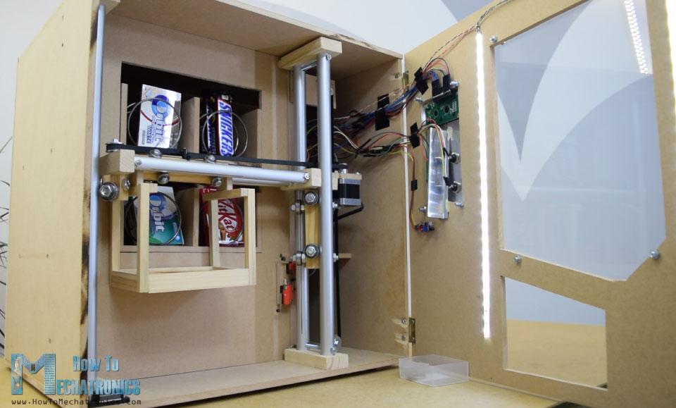
自動(dòng)售貨機(jī)具有四個(gè)連續(xù)旋轉(zhuǎn)伺服電機(jī)控制的四個(gè)出料單元、步進(jìn)電機(jī)控制的載體系統(tǒng)、液晶顯示器、四個(gè)選擇物品的按鈕和硬幣檢測器。
你現(xiàn)在可能會(huì)想,這個(gè)自動(dòng)售貨機(jī)沒有那么有用,是的,你可能是對的。但我的想法是讓這個(gè)項(xiàng)目更有趣或者更復(fù)雜,這樣你就能學(xué)到更多新東西。我認(rèn)為這個(gè)項(xiàng)目的想法可以很好的為電子或機(jī)電一體化的學(xué)生考慮建設(shè)一個(gè)作為他們的最后一年的項(xiàng)目,以及任何阿杜諾愛好者。
建造自動(dòng)售貨機(jī)
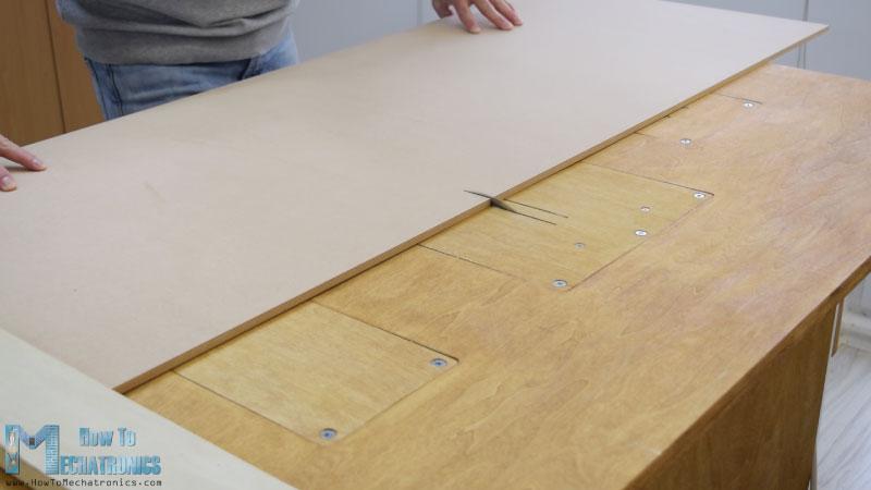
我從切割8毫米厚的中密度纖維板開始。
我以前做了一個(gè)三維模型的機(jī)器,從那里我得到了所有的測量。您可以從下面的鏈接下載三維模型。
我用圓鋸切割中密度纖維板。實(shí)際上這是一個(gè),由我的搭檔Marija制作,在她的YouTube頻道上有一段DIY視頻 .
在用圓鋸切割了所有的面板之后,我繼續(xù)用倒置的拼圖在一些面板上開孔。
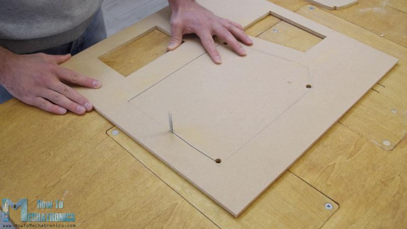
實(shí)際上,一個(gè)拼圖甚至可以用于前一步,以防你沒有圓鋸。我也用拼圖切割有好幾個(gè)切口的小零件。但是,請注意,這些是危險(xiǎn)的機(jī)器,所以在使用它們時(shí)需要非常小心。
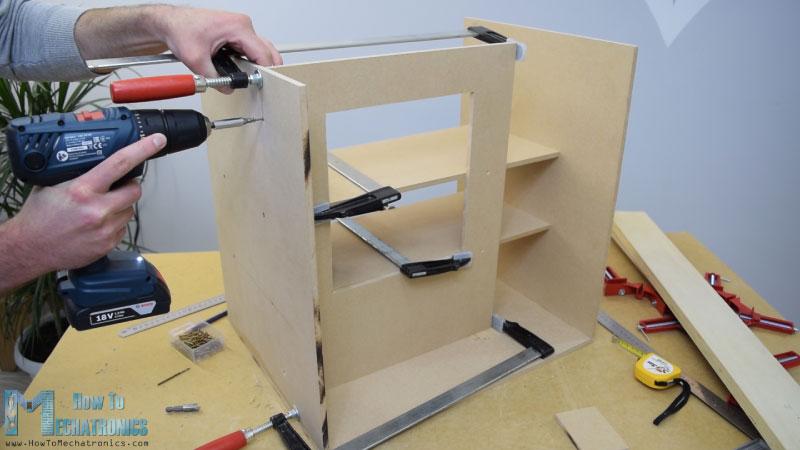
當(dāng)我準(zhǔn)備好所有的MDF部件后,我開始用一些木膠和螺絲組裝它們。為了緊固面板,我用了90度角夾鉗。使用無繩鉆,我首先做了試點(diǎn)孔,然后做了柜臺(tái)下沉和螺絲3毫米的螺絲到位。我用同樣的方法組裝了所有的面板,其中一些面板我還使用了一些F夾具。
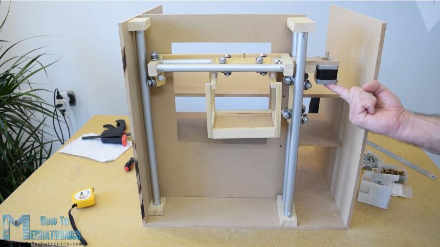
軌道系統(tǒng)
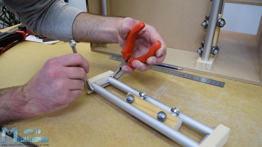
在裝配的這一點(diǎn)上,我將繼續(xù)制作軌道系統(tǒng)。為此,我使用鋁管,我用金屬手鋸將它們切割成一定的尺寸。水平軌道的管道直徑為16 mm,而垂直軌道的管道直徑為20 mm。在一個(gè)18毫米的實(shí)木板上,我用福斯特納鉆頭為管子做了槽,然后把管子連在上面。
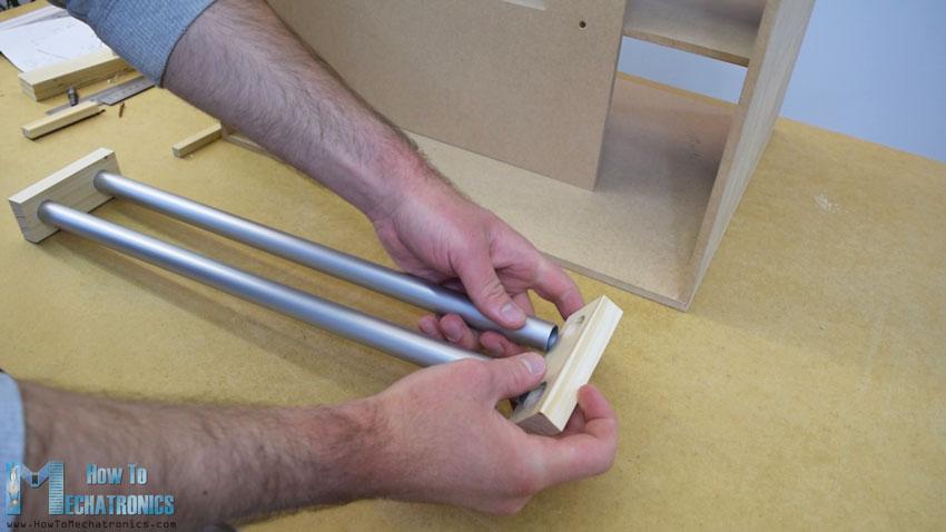
水平軌道由兩根27厘米長的管子組成,而垂直軌道由三根45厘米長的管子組成。
接下來是滑塊,下面是我如何制作的。我用21×21厘米的木板在上面打了8毫米的洞。
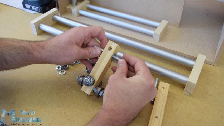
然后我通過這些孔插入8毫米螺紋桿,并用墊圈和螺母固定22毫米軸承。至于水平滑塊,我使用了相同的方法,但直徑較小的軸承為16毫米。
當(dāng)我把滑塊插入管軌之間時(shí),我發(fā)現(xiàn)它有點(diǎn)松。為了解決這個(gè)問題,我不得不縮短兩條鐵軌之間的距離。所以我先是擴(kuò)大了管子的槽,然后在管子上做了垂直的槽,最后用一根螺紋桿把兩個(gè)管子的軌道固定得更緊。在這之后,滑塊不再松動(dòng),它們正常工作。
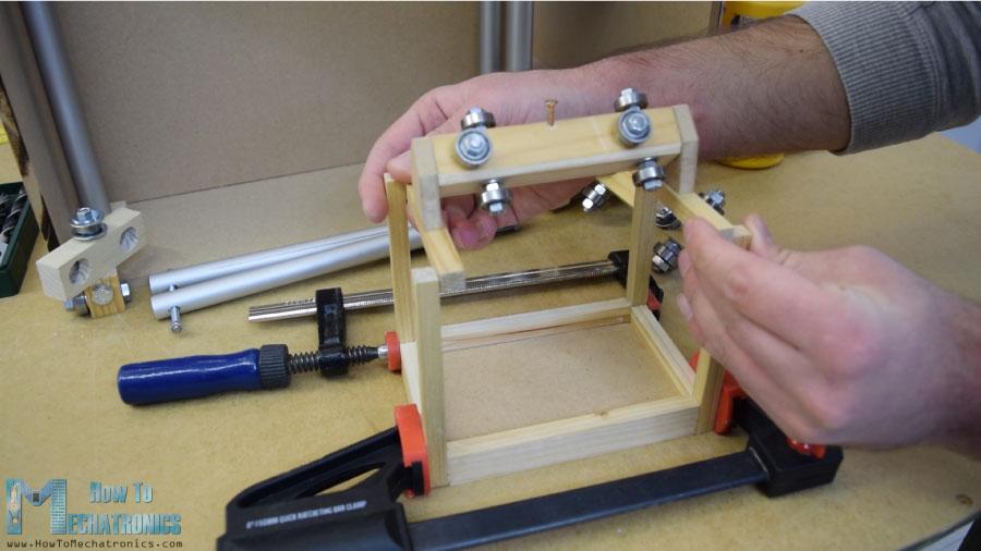
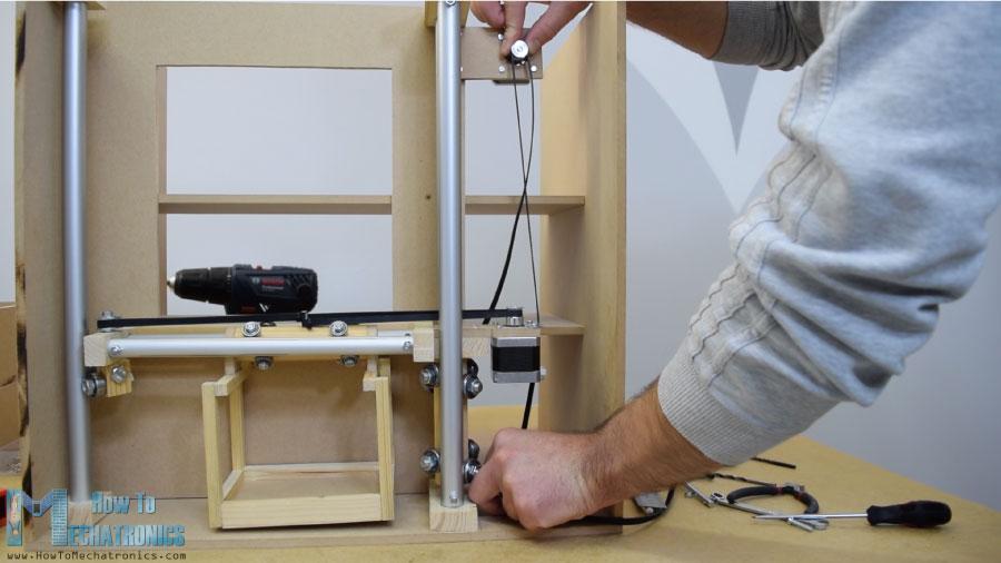
然而,在這一點(diǎn)上,我不得不拆開軌道,以便添加其他元素。首先,我添加了一個(gè)5毫米的螺栓在左側(cè)的軌道,我將附加一個(gè)滑輪的水平同步帶,以及兩個(gè)軸承將滑動(dòng)在左側(cè)垂直軌道。
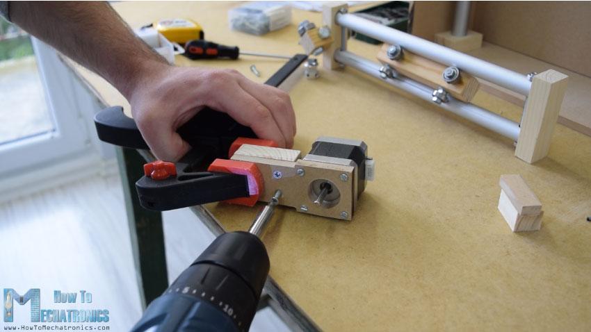
在另一個(gè)右側(cè)的軌道,我不得不附加步進(jìn)電機(jī)水平運(yùn)動(dòng)。首先,我把電機(jī)固定在一塊8毫米的中密度纖維板上,然后在上面加了一塊支撐木,還把開槽的部分固定在上面。最后,我用木膠和兩個(gè)螺絲將整個(gè)組件連接到垂直滑塊上。
接下來,我繼續(xù)在水平滑塊上添加容器。為此,我用了一些小木片,用木膠把它們連接起來。一旦我完成了這項(xiàng)工作,我就準(zhǔn)備組裝鐵路系統(tǒng)。我用了一些環(huán)氧樹脂在軌道槽,并添加了一個(gè)額外的木板,以使整個(gè)軌道系統(tǒng)更硬。
在下一步中,我將組件插入垂直軌道之間,并將其固定到位。滑塊和導(dǎo)軌系統(tǒng)的最終結(jié)果是工作良好。
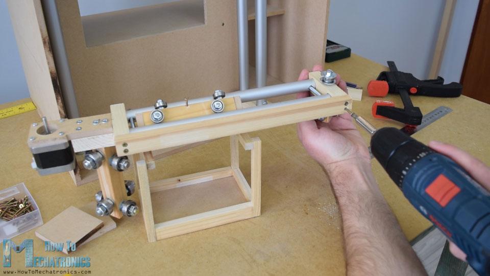
我繼續(xù)安裝水平同步帶。我測量了我需要的長度,剪成一定的尺寸,然后用一個(gè)拉鏈把它固定在滑塊上。至于垂直滑塊,我用一塊中密度纖維板和一些螺栓將步進(jìn)電機(jī)安裝在機(jī)器頂部。在底部,我連接了滑輪,并以類似的方式安裝了正時(shí)皮帶。
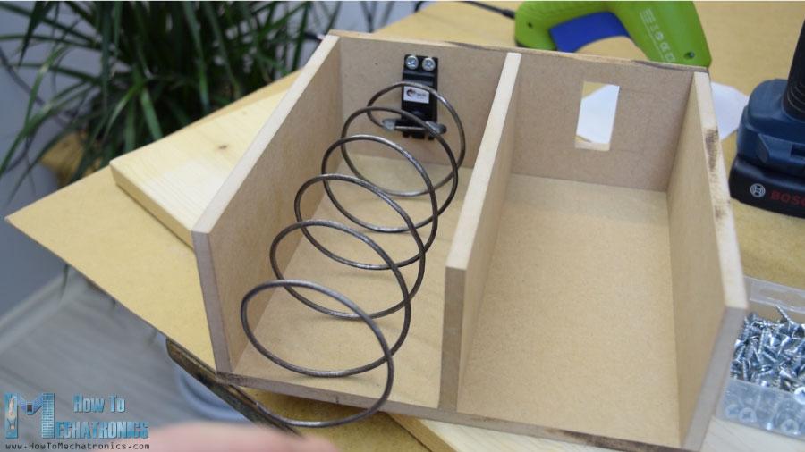
卸料裝置
接下來,我轉(zhuǎn)到卸料單元。我用3毫米厚的金屬絲做了一個(gè)螺旋線圈,把它包裹在一個(gè)直徑7厘米的噴漆罐上。
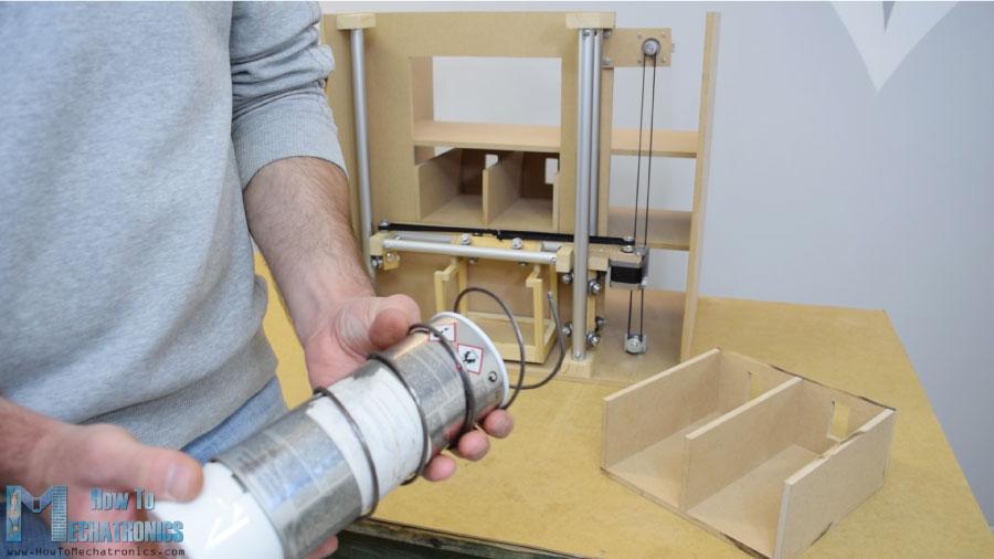
之后我用膠水槍把它固定在一個(gè)連續(xù)旋轉(zhuǎn)的伺服電機(jī)上。
前面板
下一個(gè)是前門面板,我用簡單的鉸鏈連接到自動(dòng)售貨機(jī)上,為了鎖上它,我用了一個(gè)磁性的門閂。然后我用一個(gè)5毫米厚的丙烯酸樹脂覆蓋前面的大開口,而對于右側(cè)較小的開口,我用了一塊非常錫的鋁板。我在這里為硬幣和紐扣做了4個(gè)洞. 我用鉆頭和鋼鋸做的。一旦我把電子部件連接到鋁板上,我就用5毫米的螺栓將其固定到前門板上。
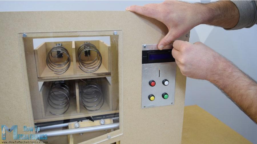
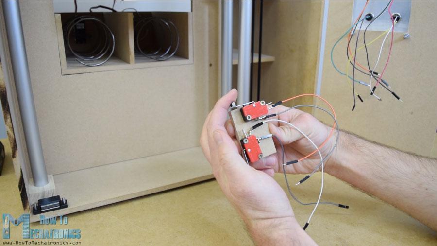
為了把載體定位到它的起始位置,我安裝了兩個(gè)微型開關(guān),對于硬幣,我粘了一個(gè)引導(dǎo)器,引導(dǎo)硬幣滑到機(jī)器底部。
當(dāng)硬幣附近有一個(gè)簡單的紅外傳感器時(shí),它會(huì)給我們一個(gè)正面的反饋。
電路圖
接下來是有趣的部分,將所有電子元件連接到Arduino板上。這是這個(gè)DIY自動(dòng)售貨機(jī)項(xiàng)目的完整電路圖。
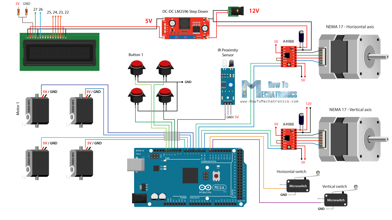
所以我們需要12伏電源,至少2安培。我們需要12伏的兩個(gè)步進(jìn)電機(jī),以及LED燈條,我將稍后附加在前門。然而,對于所有其他組件,我們需要5V,因此我使用了一個(gè)降壓轉(zhuǎn)換器將12V降壓到5V。DS04-NFC連續(xù)旋轉(zhuǎn)伺服電機(jī)由5V供電,并通過來自Arduino板的PWM信號(hào)控制,而. 四個(gè)按鈕和兩個(gè)微動(dòng)開關(guān)連接到接地和Arduino數(shù)字引腳,因此使用Arduino板的內(nèi)部上拉電阻器,我們可以很容易地檢測到何時(shí)按下它們。
您可以從以下鏈接獲取本Arduino教程所需的組件:
DC-DC LM2596降壓轉(zhuǎn)換器
16×2液晶顯示器
360度連續(xù)旋轉(zhuǎn)伺服電機(jī)
步進(jìn)電機(jī)NEMA 17
A4988步進(jìn)電機(jī)驅(qū)動(dòng)器
紅外接近傳感器
按鈕
微型限位開關(guān)
Arduino板
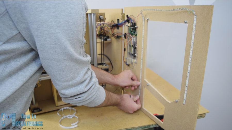
我用一些電子元件連接跨接線。它變得有點(diǎn)凌亂,有那么多電線,但一切正常。最后,我把兩個(gè)LED燈條貼在門板上,照亮自動(dòng)售貨機(jī)的內(nèi)部。
Arduino代碼
現(xiàn)在剩下的就是編程Arduino,這是我為這個(gè)項(xiàng)目制作的代碼。下面是代碼的說明。
/* DIY Vending Machine - Arduino based Mechatronics Project
by Dejan Nedelkovski, www.HowToMechatronics.com
*/
#include <LiquidCrystal.h> // includes the LiquidCrystal Library
#include <Servo.h>
LiquidCrystallcd(27, 26, 25, 24, 23, 22);// Creates an LC object. Parameters: (rs, enable, d4, d5, d6, d7)
Servo servo1, servo2, servo3, servo4;// DS04-NFC motors
// Stepper motors pins
#define dirPinVertical 0
#define stepPinVertical 1
#define dirPinHorizontal 2
#define stepPinHorizontal 3
#define coinDetector 9
#define button1 13
#define button2 12
#define button3 11
#define button4 10
#define microSwitchV 15
#define microSwitchH 14
intbuttonPressed;
voidsetup(){
lcd.begin(16, 2);// Initializes the interface to the LCD screen, and specifies the dimensions (width and height) of the display
servo1.attach(4);
servo2.attach(5);
servo3.attach(6);
servo4.attach(7);
pinMode(dirPinVertical, OUTPUT);
pinMode(stepPinVertical, OUTPUT);
pinMode(dirPinHorizontal, OUTPUT);
pinMode(stepPinHorizontal, OUTPUT);
pinMode(coinDetector, INPUT);
// Activating the digital pins pull up resistors
pinMode(button1, INPUT_PULLUP);
pinMode(button2, INPUT_PULLUP);
pinMode(button3, INPUT_PULLUP);
pinMode(button4, INPUT_PULLUP);
pinMode(microSwitchV, INPUT_PULLUP);
pinMode(microSwitchH, INPUT_PULLUP);
// Vertical starting position
digitalWrite(dirPinVertical, HIGH);// Set the stepper to move in a particular direction
while(true){
if(digitalRead(microSwitchV)== LOW){// If the micro switch is pressed, move the platfor a little bit up and exit the while loop
moveUp(70);
break;
}
// Move the carrier up until the micro switch is pressed
digitalWrite(stepPinVertical, HIGH);
delayMicroseconds(300);
digitalWrite(stepPinVertical, LOW);
delayMicroseconds(300);
}
// Horizontal starting position
digitalWrite(dirPinHorizontal, LOW);
while(true){
if(digitalRead(microSwitchH)== LOW){
moveLeft(350);
break;
}
digitalWrite(stepPinHorizontal, HIGH);
delayMicroseconds(300);
digitalWrite(stepPinHorizontal, LOW);
delayMicroseconds(300);
}
}
voidloop(){
// Print "Insert a coin!" on the LCD
lcd.clear();
lcd.setCursor(0, 0);
lcd.print("Insert a coin!");
// Wait until a coin is detected
while(true){
if(digitalRead(coinDetector)== LOW){// If a coin is detected, exit the from the while loop
break;
}
}
delay(10);
lcd.clear();
lcd.setCursor(0, 0);
lcd.print("Select your item");
lcd.setCursor(0, 1);
lcd.print(" 1, 2, 3 or 4?");
// Wait until a button is pressed
while(true){
if(digitalRead(button1)== LOW){
buttonPressed = 1;
break;
}
if(digitalRead(button2)== LOW){
buttonPressed = 2;
break;
}
if(digitalRead(button3)== LOW){
buttonPressed = 3;
break;
}
if(digitalRead(button4)== LOW){
buttonPressed = 4;
break;
}
}
// Print "Delivering..."
lcd.clear();
lcd.setCursor(0, 0);
lcd.print("Delivering...");
// Depending on the pressed button, move the carrier to that position and discharge the selected item
switch(buttonPressed){
case1:
// Move the container to location 1
moveUp(4900);// Move up 4900 steps (Note: the stepper motor is set in Quarter set resolution)
delay(200);
moveLeft(1700);// Move left 1700 steps
delay(300);
// Rotate the helical coil, discharge the selected item
servo1.writeMicroseconds(2000);// rotate
delay(950);
servo1.writeMicroseconds(1500);// stop
delay(500);
// Move the container back to starting position
moveRight(1700);
delay(200);
moveDown(4900);
break;
case2:
// Move the container to location 2
moveUp(4900);
delay(200);
// Rotate the helix, push the selected item
servo2.writeMicroseconds(2000);// rotate
delay(950);
servo2.writeMicroseconds(1500);// stop
delay(500);
moveDown(4900);
break;
case3:
// Move the container to location 3
moveUp(2200);
delay(200);
moveLeft(1700);
delay(300);
// Rotate the helix, push the selected item
servo3.writeMicroseconds(2000);// rotate
delay(950);
servo3.writeMicroseconds(1500);// stop
delay(500);
// Move the container back to starting position
moveRight(1700);
delay(200);
moveDown(2200);
break;
case4:
// Move the container to location 4
moveUp(2200);// Move verticaly 4800 steps
delay(200);
// Rotate the helix, push the selected item
servo4.writeMicroseconds(2000);// rotate
delay(950);
servo4.writeMicroseconds(1500);// stop
delay(500);
moveDown(2200);
break;
}
lcd.clear();// Clears the display
lcd.setCursor(0, 0);
lcd.print("Item delivered!");// Prints on the LCD
delay(2000);
}
// == Custom functions ==
voidmoveUp(intsteps){
digitalWrite(dirPinVertical, LOW);
for(intx = 0; x<steps; x++){
digitalWrite(stepPinVertical, HIGH);
delayMicroseconds(300);
digitalWrite(stepPinVertical, LOW);
delayMicroseconds(300);
}
}
voidmoveDown(intsteps){
digitalWrite(dirPinVertical, HIGH);
for(intx = 0; x<steps; x++){
digitalWrite(stepPinVertical, HIGH);
delayMicroseconds(300);
digitalWrite(stepPinVertical, LOW);
delayMicroseconds(300);
}
}
voidmoveLeft(intsteps){
digitalWrite(dirPinHorizontal, HIGH);
for(intx = 0; x<steps; x++){
digitalWrite(stepPinHorizontal, HIGH);
delayMicroseconds(300);
digitalWrite(stepPinHorizontal, LOW);
delayMicroseconds(300);
}
}
voidmoveRight(intsteps){
digitalWrite(dirPinHorizontal, LOW);
for(intx = 0; x<steps; x++){
digitalWrite(stepPinHorizontal, HIGH);
delayMicroseconds(300);
digitalWrite(stepPinHorizontal, LOW);
delayMicroseconds(300);
}
}
源代碼說明
首先,我們需要包括伺服和液晶庫,定義LCD引腳、四個(gè)伺服電機(jī)、步進(jìn)電機(jī)引腳、硬幣探測器以及四個(gè)按鈕和兩個(gè)微型開關(guān)。
在設(shè)置部分,我們?yōu)樯厦嫣岬降拿總€(gè)引腳設(shè)置引腳模式。我們可以注意到,對于按鈕和微型開關(guān)引腳,我們激活了內(nèi)部上拉電阻器。這意味著這些引腳的邏輯電平將一直處于高位,一旦我們按下它們,邏輯電平將下降到低位。
在我們進(jìn)入主回路之前,我們還將載波設(shè)置到由兩個(gè)微動(dòng)開關(guān)定義的起始位置。因此,在while循環(huán)中,我們繼續(xù)將載體移動(dòng)到其起始位置,一旦按下兩個(gè)微動(dòng)開關(guān),電機(jī)將停止并移動(dòng)到所需的啟動(dòng)位置。
// Vertical starting position
digitalWrite(dirPinVertical, HIGH);// Set the stepper to move in a particular direction
while(true){
if(digitalRead(microSwitchV)== LOW){// If the micro switch is pressed, move the platfor a little bit up and exit the while loop
moveUp(70);
break;
}
// Move the carrier up until the micro switch is pressed
digitalWrite(stepPinVertical, HIGH);
delayMicroseconds(300);
digitalWrite(stepPinVertical, LOW);
delayMicroseconds(300);
}
// Horizontal starting position
digitalWrite(dirPinHorizontal, LOW);
while(true){
if(digitalRead(microSwitchH)== LOW){
moveLeft(350);
break;
}
digitalWrite(stepPinHorizontal, HIGH);
delayMicroseconds(300);
digitalWrite(stepPinHorizontal, LOW);
delayMicroseconds(300);
}
在主程序中,首先在LCD上打印"插入硬幣"消息。然后我們被困在while循環(huán)中。一旦插入一個(gè)硬幣,它通過接近傳感器,硬幣探測器引腳的邏輯狀態(tài)將下降到低,在這種情況下,我們將使用break語句退出while循環(huán)。
// Wait until a coin is detected
while(true){
if(digitalRead(coinDetector)== LOW){// If a coin is detected, exit the from the while loop
break;
}
}
我們在循環(huán)中選擇另一條信息然后打印。
// Wait until a button is pressed
while(true){
if(digitalRead(button1)== LOW){
buttonPressed = 1;
break;
}
if(digitalRead(button2)== LOW){
buttonPressed = 2;
break;
}
if(digitalRead(button3)== LOW){
buttonPressed = 3;
break;
}
if(digitalRead(button4)== LOW){
buttonPressed = 4;
break;
}
}
這個(gè)while循環(huán)等待我們按下四個(gè)按鈕中的任何一個(gè),一旦我們按下了,我們就會(huì)退出并打印消息"Delivering"。
現(xiàn)在,根據(jù)按下的按鈕,我們在switch語句中執(zhí)行一次case。如果我們按下了第一個(gè)按鈕,運(yùn)營商將開始使用定制的"moveUp()"函數(shù)上移。
switch(buttonPressed){
case1:
// Move the container to location 1
moveUp(4900);// Move up 4900 steps (Note: the stepper motor is set in Quarter set resolution)
delay(200);
moveLeft(1700);// Move left 1700 steps
delay(300);
// Rotate the helical coil, discharge the selected item
servo1.writeMicroseconds(2000);// rotate
delay(950);
servo1.writeMicroseconds(1500);// stop
delay(500);
// Move the container back to starting position
moveRight(1700);
delay(200);
moveDown(4900);
break;
}
如果我們看一下這個(gè)函數(shù),我們可以看到它只是將步進(jìn)電機(jī)設(shè)置為向特定的方向移動(dòng),并使我們輸入的步數(shù)作為參數(shù)。
voidmoveUp(intsteps){
digitalWrite(dirPinVertical, LOW);
for(intx = 0; x<steps; x++){
digitalWrite(stepPinVertical, HIGH);
delayMicroseconds(300);
digitalWrite(stepPinVertical, LOW);
delayMicroseconds(300);
}
}
我們可以注意到,我設(shè)置了A4988步進(jìn)驅(qū)動(dòng)器的工作在四分之一步的分辨率,和一些品味,我得出結(jié)論,我需要4900步,以使載體達(dá)到較高的位置。以類似的方式,我們將載體向左移動(dòng),直到到達(dá)位置1。
緊接著,我們旋轉(zhuǎn)連續(xù)旋轉(zhuǎn)電機(jī)950毫秒,使螺旋線圈完成一個(gè)完整的循環(huán)。
// Rotate the helical coil, discharge the selected item
servo1.writeMicroseconds(2000);// rotate
delay(950);
servo1.writeMicroseconds(1500);// stop
請注意,這些值有時(shí)會(huì)變化,并取決于電機(jī)本身。使用moveRight()和moveDown()自定義函數(shù),我們將載體帶回起始位置。以同樣的方式,我們可以卸下這四個(gè)項(xiàng)目中的任何一個(gè)。
最后我們只打印消息"項(xiàng)目已送達(dá)"。
*博客內(nèi)容為網(wǎng)友個(gè)人發(fā)布,僅代表博主個(gè)人觀點(diǎn),如有侵權(quán)請聯(lián)系工作人員刪除。