音頻鑒定報告的DS1802雙數字音頻電位-Audio Cha

Cross-Talk
Cross-talk measurements were performed using the test configuration diagrams of Figures 11 and 12. The cross-talk analysis is performed by evaluating signals taken from both wipers of the DS1802. In this test, potentiometer 0 is supplied a signal from the Audio Precision analyzer. This signal is returned to the analyzer via the wiper of potentiometer 0 (view either Figure 11 or 12). This signal return is connected to the audio analyzer's channel-A input.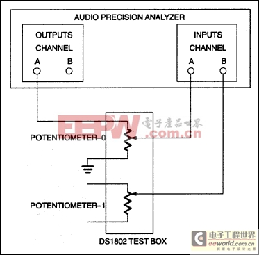
Figure 11. Cross-talk configuration potentiometer 1 open.
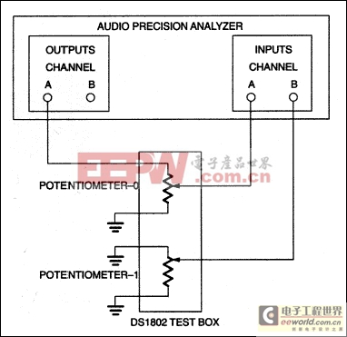
Figure 12. Cross-talk configuration potentiometer 1 grounded.
Potentiometer 1 and its wiper (primarily the wiper) are used as the comparison point for signal feedthrough. The high and low terminals, H1 and L1, are either left open circuited, as shown in Figure 11 or grounded as shown in Figure 12. The wiper of potentiometer 1 is connected to the audio analyzer's input via channel-B.
A comparison between the channel-A input and channel-B input of the audio analyzer is then made to determine the level of cross-talk. Graphical data of both the configurations of Figures 11 and 12 are presented in Figure 13.
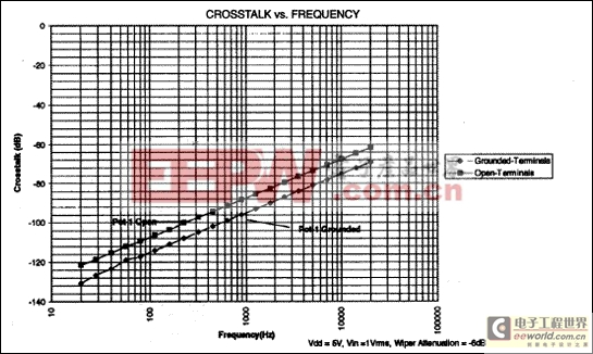
Figure 13. Cross-talk data.
Wiper Position vs. Temperature
Data is provided concerning each potentiometer's wiper position as a function of temperature. Temperatures evaluated include 0°C, 25°C, and 70°C. Data is provided in Figure 14 and is presented as a tolerance or absolute error as a function of wiper position. For example, wiper position 28 should correspond to a tolerance of 28 dB ±0.5 dB.As can be seen from graphical data, temperature has little or no effect on absolute tolerance.
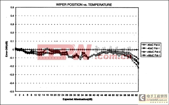
Figure 14. Wiper position vs. temperature potentiometer 0.
Device Muting Level
The DS1802 provides both a hardware and software mute capability. Data provided in Figures 15 and 16 show mute levels of a sample set of five parts. As shown, mute levels are in excess of -90.0 dB relative to wiper position-0, for both potentiometers over the given sample set. The DS1802 is specified to provide a mute capability of at least -90.0 dB.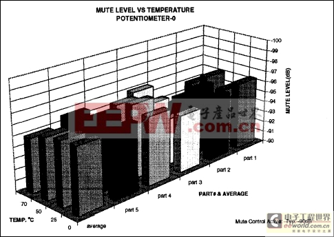
Figure 15. Device muting level—potentiometer 0.
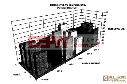
Figure 16. Device muting level—potentiometer 1.
Active Current vs. Temperature
Data for active current is provided for a supply voltage of 5 volts. This data is presented in Figure 17. The DS1802 for this test is configured for zero-crossing detect mode, and pushbutton inputs active. This configuration provides worst-case application of the part for active current usage.For information concerning pushbutton inputs or zero-crossing detection mode, refer to the data sheet of the DS1802.
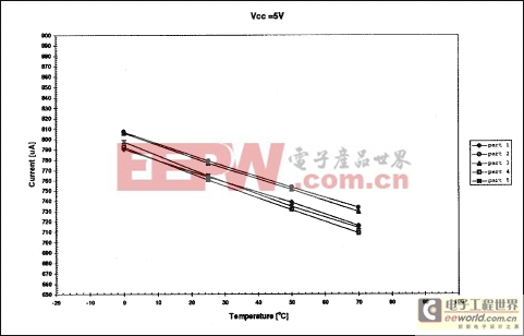
Figure 17. Active current vs.temperature.
Standby Current @ VCC
Standby current data is provided for supply voltages of VCC = +3.0 and +5.0 volts. The DS1802 configuration for this test has no activity on 3-wire serial ports, pushbutton inputs, or voltage across either potentiometer. Figures 18 and 19 provide graphical data for +3.0 and +5.0-volt operation.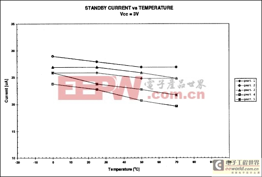
Figure 18. Standby current @ VCC = 3 volts.
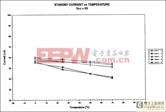
Figure 19. Standby current @ VCC = 5 volts.
Conclusions
As stated in the Purpose section of this document, data presented here represents an examination of the audio characteristics of the DS1802. The DS1802 is specified as a 50 k =dual digital potentiometer. The intended use of this data is to provide the audio designer some feel for the performance of the DS1802 in an audio application. Although not a comprehensive report, data provided examines an array of commonly sought after specifications; such as THD+N, intermodulation distortion, and cross-talk.
 Questions concerning this report or data provided in this report can be directed to 214-450-8167
Bibliography
- Bob Metzler, Audio Measurement Handbook, 1st edition, (Beaverton, Oregon: Audio Precision, 1993), p. 147.
- Bob Metzler, Audio Measurement Handbook, 1st edition, (Beaverton, Oregon: Audio Precision, 1993), p. 37-39.
- Audio Precision, User's Manual Audio Precision System One, 15th Revision, (Beaverton, Oregon: Audio Precision, November 1992), Chapter 16.


評論