MR-16 LED驅(qū)動(dòng)器和用于脈沖LED冷卻器供電的5V輔助

Abstract: This application note presents a reference design for a 4S1P MR-16 LED driver that provides 750mA to a string of four white LEDs (WLEDs). The circuit operates from a 24V source and is based around the MAX16820 hysteretic LED driver. Also included is a MAX5033 24V-to-5V, 150mA switching power supply to power a Nuventix? pulsating LED cooler.
Overview
This reference design details a driver circuit using the MAX16820 hysteretic LED driver for a 4-LED MR-16 lamp with an associated power source (MAX5033) for a pulsed air cooler.The following are the electrical input requirements and output capabilities.
VIN: 24VDC ±5%
Temperature: +80°C (max) ambient
VLED configuration: 4 LEDs in series (16VDC, max), 750mA
Auxiliary output power: 5V at 150mA (average), 300mA (peak)
The reference design is discussed in detail below, with analysis of the main circuit blocks and layout considerations.
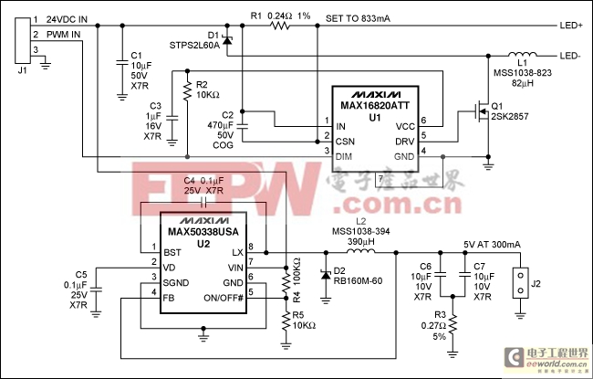
Figure 1. Schematic of the driver design.
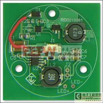
Figure 2. Photo of the PCB. The board was designed to fit directly into an MR-16 assembly.
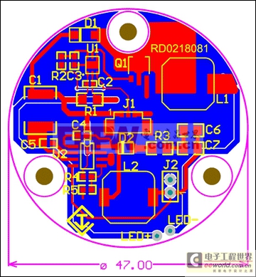
Figure 3. Revised layout of the PCB (updated from the board in Figure 2).
Design Analysis
Designed to fit directly into an MR-16 assembly, this reference design delivers 750mA to a string of 4 LEDs from a 24V power source. The MAX16820 provides hysteretic control and regulates the current through the inductor and the LEDs. Meanwhile, the MAX5033 provides power to a pulsating cooler through the J2 connector. The cooler presents a sinusoidal load of 300mA peak and 150mA average to the power supply.The R3 resistor is in the circuit to satisfy the stability requirements (with a ceramic output capacitor) of the MAX5033.
A provision was made for PWMing, but not tested. The center pin of J1 was routed directly to the DIM input of the MAX16820.
Power-Up Procedure
- Connect 4 LEDs in series to the LED+ (anode) and LED- (cathode) pins.
- Attach a 300mA load to J2.
- Attach a 24V, 1A power supply to J1.
- Turn on the power supply.
| Designator | Component | Description | Footprint | Quantity |
| C1 | Nonpolarized capacitor | 10μF, 50V, X7R | 2220 | 1 |
| C2 | Nonpolarized capacitor | 470pF, 50V, COG | 0402 | 1 |
| C3 | Nonpolarized capacitor | 1μF, 16V, X7R | 0603 | 1 |
| C4, C5 | Nonpolarized capacitors | 0.1μF, 25V, X7R | 0603 | 2 |
| C6, C7 | Nonpolarized capacitors | 10μF, 10V, X7R | 1206 | 2 |
| D1 | Schottky diode | STPS2L60A | SMA | 1 |
| D2 | Schottky diode | RB160M-60 | SOD123F | 1 |
| J1 | 3 x 1 connector | — | 1.25mm | 1 |
| J2 | 2 x 1 connector | — | 100mil | 1 |
| L1 | Inductor | 82μH, MSS1038-823 | 10.2mm x 10mm | 1 |
| L2 | Inductor | 390μH, MSS1038-394 | 10.2mm x 10mm | 1 |
| Q1 | n-channel MOSFET | 2SK2857 | SOT89 | 1 |
| R1 | Resistor | 0.24Ω, 1% | 1206 | 1 |
| R2 | Resistor | 10kΩ, 1% | 0603 | 1 |
| R3 | Resistor | 0.27Ω, 5% | 1206 | 1 |
| R4 | Resistor | 100kΩ, 1% | 0603 | 1 |
| R5 | Resistor | 10kΩ, 1% | 0603 | 1 |
| U1 | LED driver | MAX16820ATT | 6-TDFN | 1 |
| U2 | Buck DC-DC converter | MAX5033BUSA | 8-SO | 1 |


評(píng)論