混合電路驅動器的類型和數量的LED-Circuit Driv

The circuit in Figure 1 drives the LED strings via transistors Q1-Q4, which operate as current mirrors. This technique offers the following advantages:
- eliminates the current-limiting resistors
- drives groups of dissimilar LEDs
- requires just one power supply voltage
- allows each string to operate at a different current
- and allows the brightness of all the LEDs to be adjusted with one control point (U1's ADJ pin).
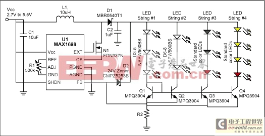
Figure 1. In this LED-drive circuit, a switching converter (U1) and associated components let you mix LED quantities and types.
Transistors Q2-Q4 mirror the current in diode-connected transistor Q1. Note that the Q1 current-set string (LEDs D3-D5) should have an equal or larger voltage than that of subsequent LED strings. (If it doesn't, the current-mirrored strings may not have enough voltage overhead to function properly.) You can easily meet that requirement in the first string, by placing either LEDs with larger forward voltage drops (such as the approximate 2.8V to 3.7V range of white LEDs), or a greater number of similar LEDs. Then, the subsequent strings with lower voltage burdens can be easily accommodated.
The matched-transistor current mirrors maintain a constant and equal current in all LEDs, regardless of quantity and type. That configuration allows the use of a single power supply and a single point for adjusting LED brightness.
Any power difference between the reference string and a mirrored string is dissipated in the current-mirror transistor for that string: Pmax (transistor) = (VOUT - 300mV - VLEDs) × ILEDMAX. The current-sense resistor value is R2 = 300mV/ILEDMAX, where ILEDMAX is the sum of currents from all the strings. (For a comprehensive circuit and parts list, refer to Maxim's MAX1698 EVKit data sheet.)
When driving the same LEDs without the current mirror one can reduce power dissipation in the sense resistor and ballast resistors by substituting a micro-power op amp across the current-sense resistor (Figure 2). That circuit improves efficiency by reducing the resistor values and their associated loss. Gaining up the current-sense signal by approximately 16 allows an equivalent reduction in the value of R2 and the ballast resistors.
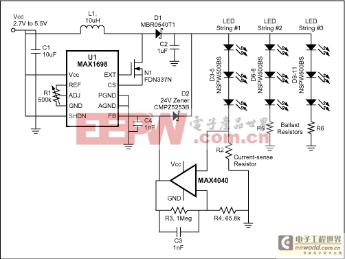
Figure 2. Modifying Figure 1 as shown reduces the overall power dissipation in a standard application.
A typical value for R2 is 15Ω, which represents a loss of 18mW (i.e., 20mA2 × 15Ω for each of three resistors). If R2 = R5 = R6 = 0.931Ω, then the resistor power loss drops to 1.12mW. The op amp draws only 20μA maximum, which is a dissipation of 100μW.
A similar version of this article appeared in the October 3, 2002 issue of EDN magazine.


評論