簡單電力場效應管驅動器是孤立的和DC耦合-Simp

Designers of power electronic circuits must often drive power switches that feed DC, AC, or power signals to a variety of loads. Logic-level electronic circuits always provide the driving signals. In general, however, the power sources and their loads have reference levels different from that of the control circuitry (ground).
An isolated transformer-driver IC (MAX845) serves as a control-signal generator. The signal is coupled to the gate of the MOSFET(s) with a very small transformer, and switched ON/OFF using the IC's SHDN input. The resulting gate driver (Figure 1) can control power loads continuously ON or continuously OFF, and is relatively fast in switching between ON and OFF. The isolated gate control signal is obtained by rectification in the secondary of T1, with a diode (D5) and transistor (Q1) to accelerate turn-off.
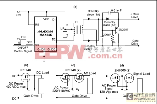
Figure 1. This transformer-coupled FET driver (a) suits a variety of applications: DC power and load (b); AC power and load (c); and AC power signal and load (d).
The driver is simple and physically small because of its tiny package (an 8-pin mMAX) and its high operating frequency (450kHz minimum), which in turn allows use of a very small transformer. Turn-on and turn-off times for an IRF740 MOSFET are about 2μs, with a propagation delay of 0.5μs. The capacitance between control-circuit ground and the power circuit being controlled is the primary-to-secondary interwinding capacitance of T1, which can be as low as a few picofarads. That capacitance is important in some applications as a measure of the high-frequency insulation between the power and control sections.
Figure 1 illustrates possible circuit configurations for switching DC, power AC, and power signals. A given selection of heat sinking and power devices limits the maximum voltage and current that can be handled. The maximum voltage difference between power circuit and control ground is determined by the maximum voltage specifications of T1's primary/secondary insulation. Maximum switching speed is limited by the total gate charge to be switched on the power switching MOSFETs. Similarly, the maximum frequency of the controlled power signals depends on the drain/source capacitance of the MOSFETs used.
A similar version of this article appeared in the January 19, 2005 issue of EE Times Planet Analog supplement


評論