Automotive protection circuit

A similar version of this article appeared in the November 25, 2007 issue of Machine Design magazine.
Many applications in automotive electronics require a supply voltage that remains uninterrupted during momentary power failures. For that purpose, the Figure 1 circuit maintains power to the load regardless of momentary shorts or opens in the supply voltage. The low-current overvoltage-protection IC (MAX6495) also protects the load against transient voltages up to 72V.
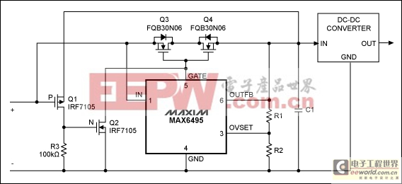
Figure 1.This automotive power supply withstands input-voltage transients up to 72V, and maintains a regulated output despite brief shorts and opens in the input supply voltage.
The circuit operates from a nominal 13V input voltage. During momentary power interruptions, the large capacitance at the input to the DC-DC converter (C1) provides ride-through capability by supplying the converter for periods up to 5 milliseconds or so. During a momentary short-circuit of source voltage, the circuit again shields the converter output from interruption by preventing discharge of C1 via the shorted supply.
When the 13V input drops because of a short to ground, storage capacitor C1 must be prevented from back discharge through the short. This is accomplished by transistors Q1 and Q2: the short on Q1's gate turns it on, connecting the ~13V on C1 to the gate of Q2, which turns Q2 on. Q2 shorts to ground the internal charge pump at GATE, which drives the pass transistors Q3 and Q4 to cutoff by quickly discharging their gate capacitance. With Q3–Q4 turned off, C1 cannot discharge through the short, and the output voltage in Figure 1 rides through the disturbance unaffected (Figure 2).
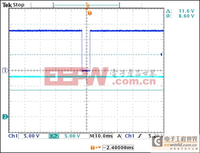
Figure 2. The output voltage in Figure 1 (bottom trace) is unaffected by a brief short in the input voltage (top trace).
The total gate charge for transistors Q3 and Q4 should be low, to enable fast turn-on and turn-off times, and VDS(max) should be high enough for the highest voltage transient expected. RDS(on) for Q3–Q4 should be low to minimize voltage drop and power dissipation.
The value for C1 depends on the load power, the maximum tolerable voltage droop (Figure 3), and the expected duration for loss of input voltage (ride-through time):
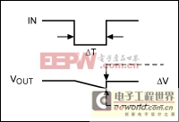
Figure 3. These waveforms define voltage droop (ΔV), the decline of capacitor voltage due to discharge during a time interval ΔT.
Energy stored in the capacitors is ?CV2, i.e., E = PΔt = ?C(ΔV)2. Therefore, C = (2PΔt)/[(ΔV)2].
Where
E = stored energy
C = capacitance
ΔV = maximum tolerable droop
P = Power used by load
ΔT = expected duration of input-voltage loss


評論