心型閃爍燈電路

Buying a gift for someone special or a loved one can sometimes be difficult or expensive. The flashing heart is the answer. It is easy to build and even the inexperienced hobbyist should be able to build it. The estimated cost for the circuit is $25 if all the parts are purchased new. With The Flashing Heart, you can get your message across in bright lights.
本文引用地址:http://www.104case.com/article/169407.htmCircuit Description
The Circuit Diagram is shown in Figure 1. It consists of a 4047 low-power monostable/astable multivibrator, IC1, used in the astable mode to provide the timing pulses to control the flash rate of the LEDs. To accomplish the astable mode, pins 4, 5, 6, and 14 are connected to +12VDC and pins 7, 8, 9, and 12 are connected to ground. Pins 1 and 3 are connected to C2 and pins 2 and 3 are connected to potentiometer R9. A fixed value resistor can be used in place of the potentiometer R9, if the flash rate does not need to be adjusted. These three pins make up the R-C timing circuit. The output pulses from the 4047 are taken from pins 10, 11, and 13. Pin 10 is the Q output and pin 11 is the Q-not output. These two pins are onnected to R6 and R7 respectively.
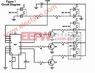
The collectors of Q2 and Q3 are connected to R4 and R5 respectively, which are connected to the cathodes of the Yellow LEDs. Pin 13 is the oscillator output and is connected to R8, which is connected to the base of Q1. The collector of Q1 is connected to R3, which is connected to the cathodes of the Red LED's. The emitters of the three transistors are connected to ground. The Green LEDs are connected to R1 and R2, which are connected to +12VDC. Resistors R1-R8 are current limiting resistors and the correct wattage for these resistors should be used to prevent excessive heat. The resistive values may be changed to vary the brightness of the LEDs. The circuit is powered by PS1, a wall transformer, which is connected to a filter capacitor C1. It must be between 10 to 15 VDC and at least 500mA.
Construction
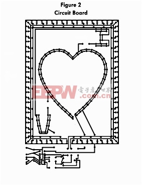
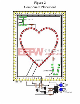
Probably the most difficult part of this project is making the printed circuit board, Figure 2. The board used in the prototype took several hours to make using dry transfers. Using a different technique, such as photo resist, may be faster for the experienced hobbyist. Once the board is etched and drilled, the jumper wires should be placed on the board and soldered, as shown on Figure 3. Next the 84 Yellow LEDs should be placed around the border of the board, followed by the 42 Red LEDs that make up the heart and then the 16 Green LEDs that make up the letters I and U. Resistors R1-R9 and capacitors C1and C2 should be placed on the board next and then the power supply, PS1. Sockets were used in the prototype for the I.C. and transistors. A socket for the I.C. is required, but the sockets for the transistors are not. Special care should be taken when handling the CMOS I.C., as a static discharge will destroy it. When you are finished soldering, check the board over for mistakes. If everything looks okay, apply power.
Operation
Once power has been applied to the circuit, the Red LEDs should all be flashing on and off together. The Yellow LEDs should be flashing on and off, but only every other Yellow LED should be on at one time. The Green LEDs will stay on at all times. The flash rate can be adjusted by turning R9. Connections for a fixed value resistor for R9 are provided on the board layout if preferred.To dress up the project, a favorite photograph can be placed in the heart, and a frame can be made to fit the circuit board.
Parts List
Resistors
R1, R2 - 470 ohm, 1/2-watt
R3-R5 - 100 ohm, 3-watt
R6-R8 - 1000 ohm, 1.4-watt
R9 - 5000 ohm potentiometer
Capacitors
C1, C2 - 100uF, 16 volts, electrolytic radial
Semiconductors
IC1 - 4047, low power monostable/astable multivibrator
Q1-Q3 - 2n3643 NPN transistor or equivalent
Diodes
LED1-LED84 - yellow light-emitting diode
LED85-LED126 - red light-emitting diode
LED127-LED142 - green light-emitting diode
Other components
PS1 - 12VDC @ 500mA wall transformer
Miscellaneous: Jumper wire, solder, printed circuit board,
drill and bits,14 pin I.C. socket, and a frame or case.

DIY機械鍵盤相關社區:機械鍵盤DIY


評論