固態功率控制器電路

Solid State Power Controller
About the Circuit
The ckt is built around two 555 timer ICs. U1 and U2. U1 is wired as a variable duty cycle oscillator with a constant time period of around 0.1 second. Duty cycle can be varied from 0 to 100 per cent by R4 potentiometer. The output of U1 (pin 3) is connected to the rest input (pin 4) of U2.
U2 is wired as a comparator with hystereis, i.e a Schmitt trigger. Diode D6 brings the potential at control voltage (pin 5) terminal at 0.7V. The threshold (pin 6) and trigger (pin 2) terminals connected together constitute the input. The output (pin 3) of the Schmitt trigger goes high when Vin equals or below 0.35V and goes low when it is equals or above 0.7V.
Transformer T1 with rectifying diodes D1 and D2 delivers unidirectional AC voltage across R1 with a peak voltage of 8.5V and 100Hz frequency. C1 is the filtering capacitor. D3 prevents the voltage across R1 from being filtered.
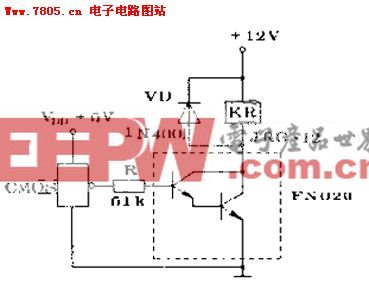
Since the input of the Schmitt trigger is connected across R1, its out put will be high when input voltage falls below 0.35V and remains so till it exceeds 0.7V. If pin 4 of U2 is left unconnected, the triac will be fired at the start of each half cycle of AC by a short pulse. Hence full power will be delivered to the load. But since output of U1 is connected to the rest input of U2, the Schmitt trigger delivers pulses to the gate of triac only when output of U1 is high. This explains how variable duty cycle zero crossover switching is accomplished. I have used a 5-amp triac, which is capable of switching loads up to 1000W. Using a triac with larger current rating can also control higher loads. Of course, size of the heat sink will have to be suitably increased.
Construction
You can build this circuit in a general purpose IC strip board. Potentiometer R4 should be linear with a plastic shaft. It can be mounted on the front portion of the enclosure, with a dial marked from 0 to 100 per cent power at, say 5 per cent intervals. If a metallic enclosure is used, care must be taken to ensure that the heat sink of triac does not touch it anywhere.
To avoid shock, do not touch any part of circuitry while in operation.
Components
U1 U2 - NE555 timer
Q1 - 5A, 400 PIV triac (BT136)
D1-D3 - IN4001 rectifier diodes
D4-D6 - IN4148 switching diodes
R1 - 5.6K
R2 -2.2K
R3 -470 ohms
R4 - 100K linear potentiometer with plastic shaft
(all resistors ¼ watt, 5% tolerance)
C1 - 1000mfd, 12V
C2 - 1mfd, 12V
C3,C4 - 0.1mfd,50V ceramic
T1 - 220V primary 6V-0-6V secondary, 150ma
F1 - 5-amp fuse

DIY機械鍵盤相關社區:機械鍵盤DIY


評論